Inductive proximity sensors are widely used in industrial automation for non-contact detection of metallic objects. As an electrical engineer with years of experience, I have encountered numerous instances where these sensors malfunction, leading to downtime and production losses. Understanding how to systematically diagnose and fix common issues is crucial for maintaining operational efficiency. This article provides a comprehensive guide on troubleshooting inductive proximity sensors, focusing on practical steps and industry best practices.
First, it is essential to recognize the typical symptoms of a faulty proximity sensor. These may include intermittent detection, failure to detect objects entirely, false triggering, or no output signal. When such issues arise, a methodical approach should be adopted to identify the root cause. Begin by checking the power supply. Ensure that the sensor is receiving the correct voltage as specified by the manufacturer. Fluctuations or incorrect voltage levels can lead to erratic behavior. Use a multimeter to verify the input voltage at the sensor's terminals. If the power supply is unstable, consider installing a regulated power source or checking for loose connections in the wiring.
Next, inspect the sensor's installation and environment. Proximity sensors are sensitive to their surroundings. Metallic debris, dust, or other contaminants on the sensing face can interfere with detection. Clean the sensor head regularly using a soft cloth and appropriate cleaning agents. Additionally, verify the mounting position. The sensor should be aligned correctly with the target object, maintaining the specified sensing distance. Misalignment or excessive gap can cause detection failures. Also, ensure that there are no other metallic objects within the sensing range that could trigger false signals.
The target object itself must be evaluated. Inductive proximity sensors are designed to detect ferrous and non-ferrous metals, but the sensing distance varies based on the material. Check if the target material matches the sensor's specifications. For instance, sensors calibrated for steel may have reduced range for aluminum. If the target material has changed, recalibrate or replace the sensor accordingly. The size and shape of the target also matter; it should be large enough to be reliably detected within the sensor's effective range.
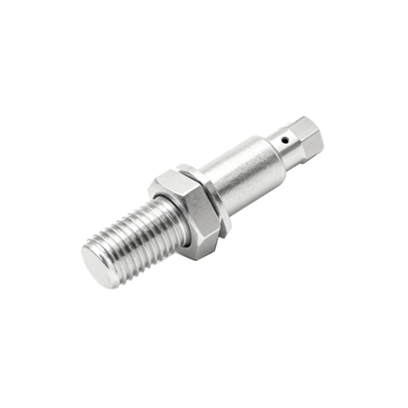
Wiring and connections are common sources of faults. Examine the cable for signs of damage, such as cuts, abrasions, or exposure to harsh chemicals. Loose or corroded terminals can disrupt signal transmission. Tighten all connections and replace damaged cables immediately. For sensors with quick-disconnect connectors, ensure they are securely mated. In systems with long cable runs, consider voltage drop issues, which can be mitigated by using thicker gauge wires or installing signal amplifiers.
Output configuration is another critical aspect. Inductive proximity sensors typically have PNP (sourcing) or NPN (sinking) outputs. Verify that the output type is compatible with the connected controller (PLC, relay, etc.). Incorrect wiring between the sensor and load can prevent proper operation. Refer to the sensor's datasheet for wiring diagrams and confirm the load specifications. If the sensor has a diagnostic LED, observe its behavior. A steady or blinking LED can indicate normal operation, while an off or erratic LED suggests a fault.
Environmental factors often contribute to sensor failures. Extreme temperatures, humidity, vibration, or electromagnetic interference (EMI) can degrade performance. Ensure the sensor is rated for the operating conditions. For high-temperature environments, select sensors with appropriate thermal ratings. Shield cables from EMI sources like motors or frequency drives. In corrosive atmospheres, use sensors with protective coatings or enclosures rated for such conditions. Regular maintenance schedules should include environmental checks to preempt potential issues.
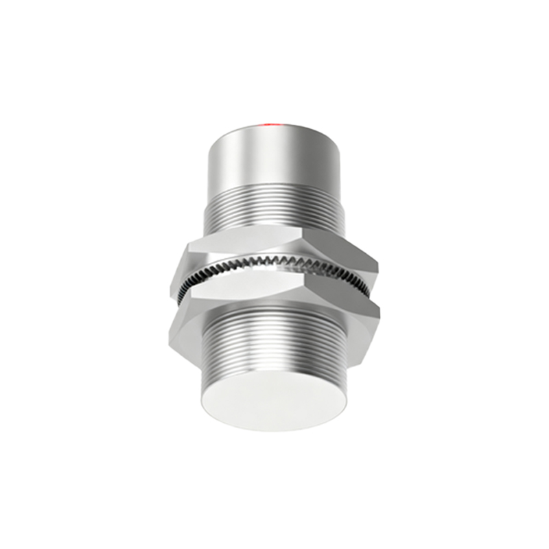
If basic checks do not resolve the fault, advanced diagnostics may be necessary. Use an oscilloscope to analyze the output signal waveform. A distorted or noisy signal could indicate internal component failure. In such cases, the sensor may need replacement. However, before discarding the sensor, test it with a known working setup to rule out external factors. Some modern sensors offer diagnostic features via IO-Link or other communication protocols, enabling detailed fault analysis through software tools.
Preventive maintenance is key to minimizing downtime. Establish a routine inspection plan that includes visual checks, cleaning, and functional tests. Keep spare sensors on hand for critical applications. Train maintenance personnel on proper handling and troubleshooting techniques. Document all fault incidents and solutions to build a knowledge base for future reference.
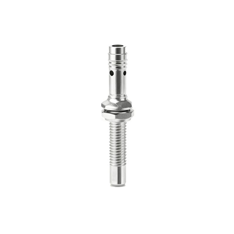
In summary, troubleshooting inductive proximity sensors involves a step-by-step process: verify power supply, inspect installation and environment, evaluate target objects, check wiring and connections, confirm output configuration, assess environmental factors, and perform advanced diagnostics if needed. By following these guidelines, engineers can quickly restore sensor functionality and ensure reliable operation in industrial settings. Remember, proactive maintenance and adherence to manufacturer specifications are essential for long-term performance.