In the field of industrial automation and precision measurement, laser sensors play a crucial role due to their high accuracy and reliability. As an electrical engineer or designer, creating accurate 3D models of these components in SolidWorks (SW) is essential for system integration, interference checking, and assembly planning. This guide provides a detailed, industry-oriented approach to modeling a typical laser sensor in SolidWorks, following best practices for design and documentation.
First, understand the sensor specifications. A standard laser sensor consists of a housing, lens assembly, emitter, receiver, and connection ports. Gather datasheets or dimensional drawings from manufacturers like Keyence, Banner, or SICK. Note key dimensions: outer diameter, length, mounting threads, and beam aperture size. Start SolidWorks and create a new part file. Set units to millimeters or inches as per your standard.
Begin with the housing. Use the Front Plane to sketch a circle representing the sensor body diameter. Extrude it to the housing length. For a cylindrical sensor, this is straightforward; if the housing is rectangular, sketch a rectangle instead. Add chamfers or fillets to edges as per the model. Next, create the mounting features. Many laser sensors have threaded mounts (e.g., M8 or M12 threads). Use the Hole Wizard in SolidWorks to add a threaded hole at the rear, ensuring correct thread specifications and depth. For bracket mounts, sketch mounting ears and extrude them.

Model the lens assembly. At the front face, sketch a smaller concentric circle for the lens aperture. Extrude it inward slightly to create a recess, then create a new plane offset forward to model the lens protrusion. Use a revolve feature if the lens is curved. Apply transparent appearance to the lens area for visual clarity. For the emitter and receiver, internal components can be simplified unless detailed analysis is needed. Create internal cylinders or blocks within the housing to represent these elements, using different colors or materials in the FeatureManager.
Add connection ports. Typically, laser sensors have cable glands or connector ports (e.g., M12 connectors). Sketch the port profile on the side or rear and extrude it. Use the Hole Wizard again for pin holes if modeling a connector. Include wire passages if required for routing. Don’t forget to model any status LEDs or indicators—small extruded circles on the housing with colored appearances.
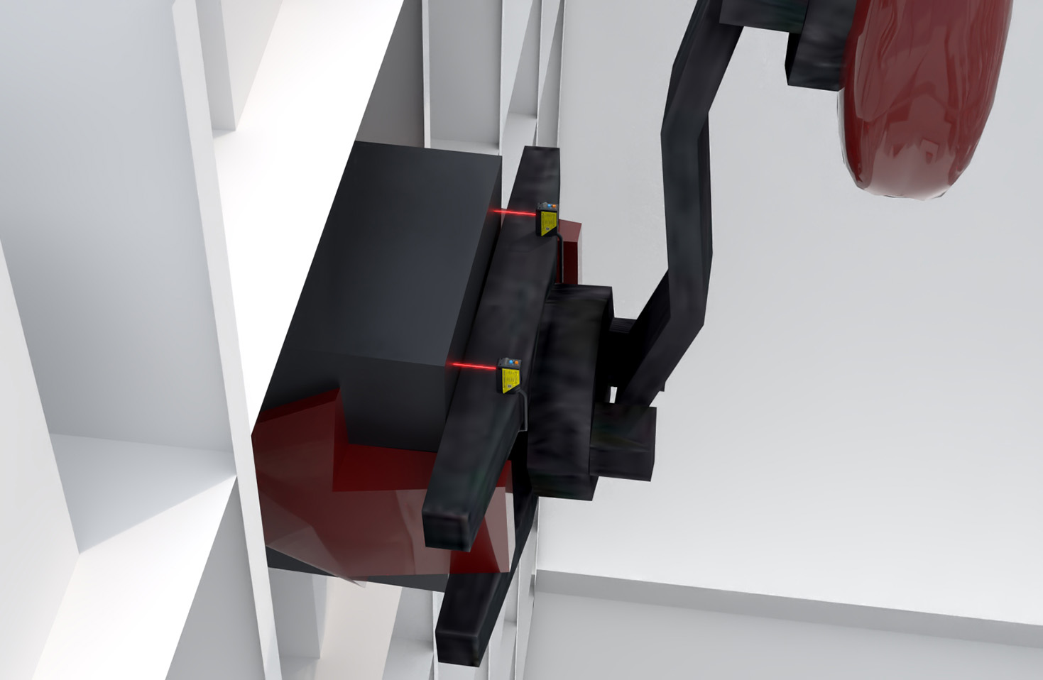
Apply materials and appearances. Assign aluminum or plastic material to the housing from the SolidWorks library. Set the lens to glass or polycarbonate. This aids in mass properties and rendering. Add decals or text for labels (e.g., model numbers) using the Sketch Text tool on surfaces.
For assembly integration, consider creating reference geometry. Add planes or axes for alignment in larger assemblies. Use configurations if modeling multiple sensor variants. Save the part and insert it into an assembly to test fits with mounting brackets or machinery.
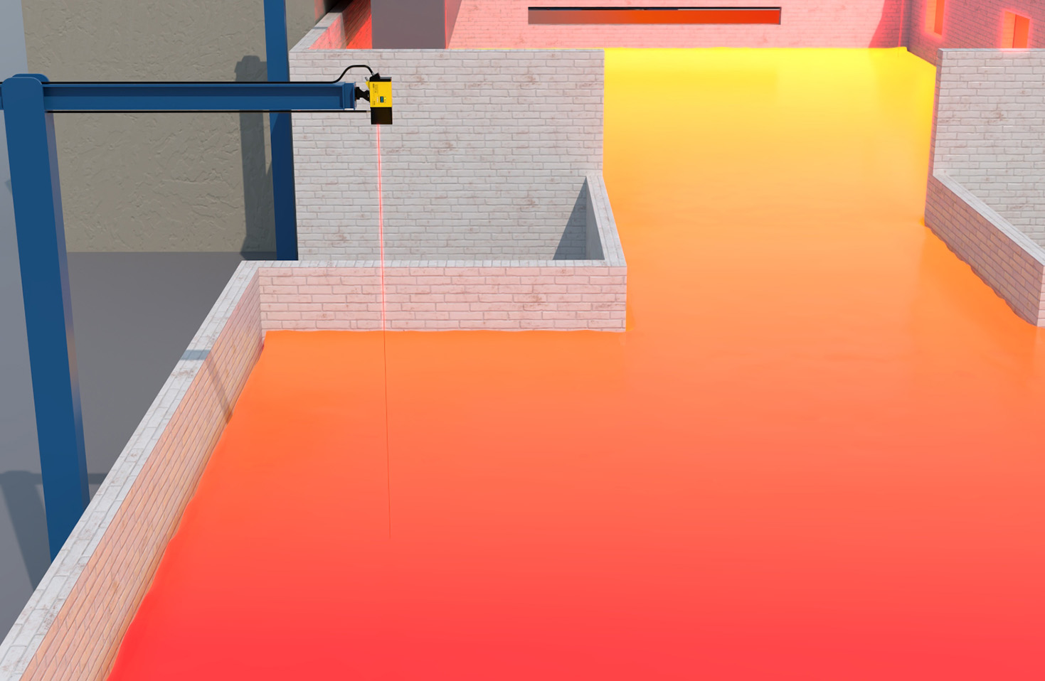
Finally, generate drawings. Create standard views, section views to show internal details, and dimension critical features. Include a bill of materials (BOM) if needed. Export as STEP or IGES for collaboration.
Best practices: Always reference manufacturer specs; use design tables for families of sensors; maintain a clean feature tree with meaningful names; check for interferences in assembly mode. This modeling process ensures your laser sensor is accurate, functional, and ready for industrial design workflows.
Remember, while this model is geometric, for advanced simulations (like beam path analysis), consider using optical modules or simplified ray tracing. SolidWorks offers basic tools, but specialized software may be required for optical performance. Keep models lightweight to avoid slowing down large assemblies. By following these steps, engineers can efficiently integrate laser sensors into digital prototypes, enhancing design accuracy and reducing prototyping costs.