In the intricate world of industrial automation, proximity sensors stand as silent sentinels, enabling precise, non-contact detection of objects. The manufacturing of these critical components is a sophisticated process that blends material science, precision engineering, and rigorous quality control. This article delves into the core technical aspects of proximity sensor production from the perspective of a seasoned electrical engineering professional.
The journey begins with the selection of core materials. The housing, typically constructed from nickel-plated brass, stainless steel, or PBT plastic, is chosen based on the required ingress protection (IP) rating and environmental resilience. Internally, the heart of an inductive proximity sensor is a ferrite core surrounded by a coil within an oscillator circuit. The manufacturing of this coil involves precise winding techniques to ensure consistent inductance and performance. For capacitive sensors, the electrode design and dielectric materials are paramount, requiring advanced molding and plating processes.
The production line is a symphony of automated and manual precision. Surface-mount technology (SMT) lines populate printed circuit boards (PCBs) with micro-components like oscillators, amplifiers, and output switching circuits. Reflow soldering follows, creating reliable electrical connections. The assembled PCB is then meticulously potted—encapsulated in a resin compound—within the sensor housing. This potting process is critical; it must provide exceptional mechanical stability, thermal conductivity, and protection against moisture, vibration, and chemical exposure without affecting the sensor's electromagnetic field. Any air bubbles or inconsistencies can lead to field failures.

Calibration and testing form the most critical phase. Each sensor undergoes a battery of automated tests. Key parameters measured include the nominal sensing distance (Sn), hysteresis, repeatability, and switching frequency. Sensors are tested under varying temperatures, voltage fluctuations, and with different target materials (e.g., steel, aluminum, copper). For inductive sensors, a standard target is moved into and out of the sensing field using precise linear actuators, while the output signal is monitored for accuracy and response time. Electrical tests check for short-circuit and overload protection, as well as current consumption. This 100% testing protocol is non-negotiable for ensuring reliability in harsh industrial environments.
Advanced manufacturing facilities are now integrating Industry 4.0 principles. IoT-enabled test stations log performance data for every unit produced, feeding information back to the design and process engineering teams for continuous improvement. Predictive maintenance on molding machines and SMT lines minimizes downtime. Furthermore, the rise of IO-Link and smart sensors has added complexity, requiring firmware programming and digital communication testing stages in the assembly process.
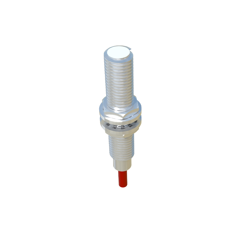
The final steps involve laser marking for model numbers, serialization, and certifications (e.g., CE, UL). Packaging is designed to prevent damage during shipping. From raw material to finished product, the entire process is governed by stringent quality management systems like ISO 9001, with traceability being a key requirement for automotive (IATF 16949) and other high-reliability industries.
In conclusion, manufacturing a high-quality proximity sensor is far more than simple assembly. It is a demanding discipline that requires deep expertise in electromagnetic theory, materials science, and precision manufacturing. The robustness and accuracy of the final product are direct results of meticulous process control, exhaustive testing, and an unwavering commitment to quality at every stage—from the initial coil winding to the final functional test. As automation demands grow smarter and more connected, sensor manufacturers continue to innovate their production methodologies to deliver the reliability that modern industry depends on.