In industrial automation and machinery control, proximity sensors are indispensable components for non-contact detection of metallic objects. Among these, the A9S series of inductive proximity sensors stands out for its robust construction, high switching frequency, and reliable performance in harsh environments. However, even the most advanced sensor requires precise calibration to ensure it operates within its specified parameters, delivering accurate and repeatable detection. This guide provides a detailed, step-by-step procedure for calibrating the A9S proximity sensor, essential knowledge for maintenance engineers, technicians, and system integrators.
The primary purpose of calibrating an A9S sensor is to adjust its sensing distance and output characteristics to match the specific application requirements. Incorrect calibration can lead to false triggers, missed detections, machine downtime, and potential safety hazards. The A9S sensor typically features an adjustable sensing range, often via a potentiometer or through teach-in methods, depending on the specific model variant (e.g., A9S1, A9S2). Before initiating any calibration procedure, ensure the sensor is correctly installed, powered with the specified voltage (commonly 10-30V DC), and free from physical damage or contamination.
Pre-Calibration Checklist:
1. Power Down: Always disconnect power to the sensor and the associated machinery. Follow Lockout-Tagout (LOTO) procedures to ensure safety.
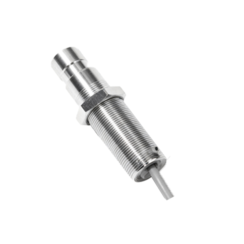
2. Consult Documentation: Refer to the specific datasheet and manual for your A9S model. Note the nominal sensing distance (Sn), recommended operating distance (Sr), and hysteresis specifications.
3. Prepare Target: Use the standard target specified by the manufacturer, typically a square of mild steel (Fe 360) with dimensions defined relative to the sensor's sensing face.
4. Environment: Ensure the calibration area is free from other metallic objects, strong electromagnetic fields, or vibrations that could interfere with the sensor's operation.
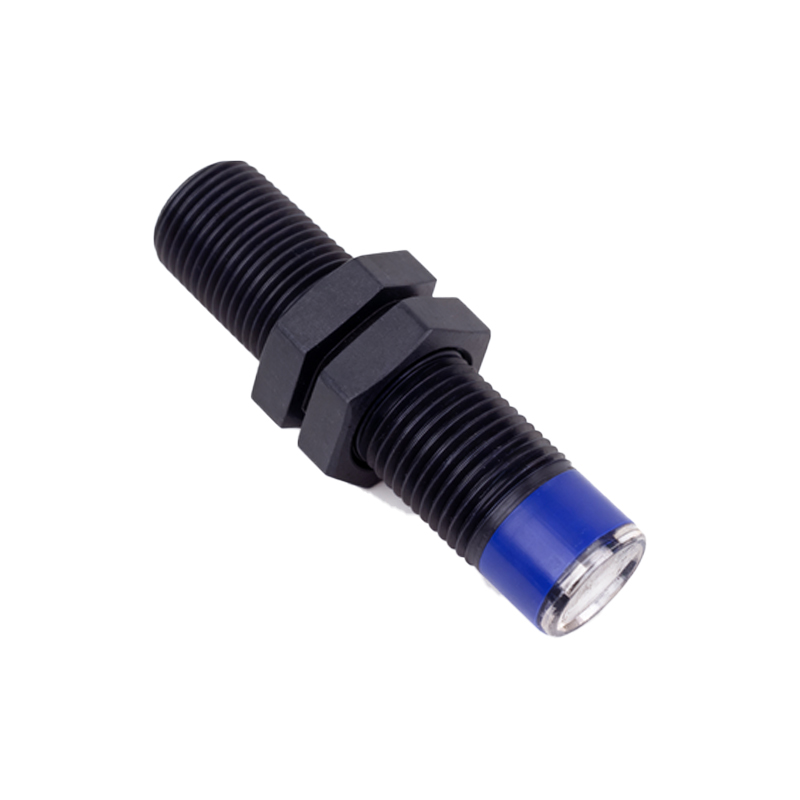
5. Tools: Have necessary tools ready, such as a non-metallic distance gauge, a digital multimeter for monitoring output voltage or current, and appropriate screwdrivers for potentiometer adjustment.
Calibration Procedure:
Step 1: Baseline Verification.
Reconnect power to the sensor only. With no target present, verify the sensor's output state. For a normally open (NO) configuration, the output should be OFF (low voltage or no current). Slowly bring the standard target axially toward the sensing face. Observe the point at which the output switches ON (e.g., 24V or sourcing current). Mark this distance. Slowly retract the target and note the point where the output switches OFF. The difference between the switch-on and switch-off points is the sensor's hysteresis, a critical characteristic for stable switching. Compare these measured values (operating point and release point) with the specifications in the datasheet.
Step 2: Potentiometer Adjustment (For Adjustable Models).
Many A9S sensors feature a multi-turn potentiometer for fine-tuning the sensing distance. Locate the adjustment screw, usually protected under a cap.
Clockwise Rotation: Typically increases the sensing distance or sensitivity. Turning it clockwise will cause the sensor to detect the target at a farther distance.
Counter-Clockwise Rotation: Decreases the sensing distance or sensitivity.
Place the target at the desired nominal operating distance from the sensor face. Adjust the potentiometer until the output just switches ON. Then, move the target slightly closer and farther to confirm a stable switching zone. Avoid setting the sensitivity at its absolute maximum, as this can make the sensor susceptible to interference from environmental factors like temperature drift or electrical noise. A good practice is to set the operating point at 80-90% of the maximum achievable distance for that specific target.
Step 3: Teach-In Method (For Smart Models).
Some advanced A9S models support a teach-in function for setting the switch point without a potentiometer. The process usually involves:
Applying power.
Presenting the target at the desired "teach" distance.
Activating the teach-in function, often by applying a voltage to a specific wire or pressing a built-in button for a set duration.
The sensor's internal circuitry learns and memorizes this distance as the new switching point. Consult the model-specific manual for the exact sequence.
Step 4: Output Verification and Load Testing.
After adjustment, test the sensor across its entire required range of motion. Use the multimeter to ensure the output voltage or current is within specification when ON and OFF. Connect the sensor to its actual load (e.g., a PLC input, relay, or solenoid valve) and perform several cycles to ensure reliable switching under real load conditions. Monitor for any chattering or inconsistent behavior.
Step 5: Documentation and