Magnetic proximity sensors are essential components in modern industrial automation, offering non-contact detection of ferromagnetic objects. These sensors operate based on the Hall effect or magnetoresistive principles, converting magnetic field changes into electrical signals. A typical magnetic proximity sensor circuit diagram includes several key elements: a sensing element (such as a Hall-effect IC or reed switch), signal conditioning circuitry, output stage, and power supply section.
The core of the circuit is the sensing element. For Hall-effect sensors, an integrated circuit like the A3144 or SS49E is commonly used. This IC generates a voltage proportional to the magnetic flux density. When a ferromagnetic object approaches, the magnetic field distorts, causing the Hall voltage to shift. This analog signal is then fed into an operational amplifier (op-amp) for amplification and noise filtering. Resistors and capacitors in this stage set the gain and bandwidth, ensuring stable operation in noisy industrial environments. For instance, a low-pass filter with a cutoff frequency of 10 kHz can eliminate high-frequency interference.
Following signal conditioning, the processed signal enters the output stage. Many industrial applications require a digital output for compatibility with PLCs (Programmable Logic Controllers) or microcontrollers. A comparator circuit, using an IC like the LM393, compares the amplified signal with a reference voltage. When the signal exceeds the threshold, the output toggles from high to low (or vice versa), indicating object detection. This output can be configured as NPN (sinking) or PNP (sourcing), depending on the system requirements. Protection components, such as flyback diodes for inductive loads or transient voltage suppressors, are often added to prevent damage from voltage spikes.
Power supply design is critical for reliability. Magnetic proximity sensors typically operate at DC voltages ranging from 5V to 24V. A voltage regulator, like the 7805 for 5V systems, ensures stable power to the sensing and conditioning circuits. Decoupling capacitors (e.g., 100nF ceramic and 10µF electrolytic) are placed near ICs to minimize noise. For battery-powered applications, low-power modes or sleep functions can be integrated to extend lifespan.
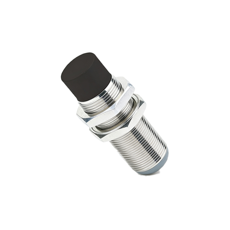
In practice, the circuit layout must consider electromagnetic compatibility (EMC). Shielding the sensor from external magnetic fields and minimizing trace lengths reduces interference. For harsh environments, conformal coating or encapsulation protects against moisture and dust. Testing involves verifying detection range, response time, and temperature stability. For example, a sensor might be calibrated to detect a steel object at 10mm with a response time under 1ms, operating from -25°C to 85°C.
Applications span various industries. In automotive systems, magnetic sensors monitor wheel speed or gear position. In manufacturing, they detect machine part presence on conveyor belts, enhancing safety and efficiency. Home appliances, like washing machines, use them for lid closure detection. Recent advancements include IoT integration, where sensors transmit data wirelessly for predictive maintenance.

Designing a magnetic proximity sensor circuit requires balancing sensitivity, power consumption, and cost. Selecting the right sensing technology—Hall-effect for precision or reed switches for simplicity—depends on the use case. Engineers must also adhere to standards like IEC 60947-5-2 for performance and safety. By optimizing the circuit diagram, these sensors provide reliable, maintenance-free operation in diverse settings, from factory floors to smart homes.