In industrial automation and control systems, proximity switch sensors are indispensable components, valued for their non-contact detection capabilities, durability, and reliability. A common, yet sometimes perplexing, issue encountered by maintenance personnel and engineers is when the built-in indicator light on a proximity sensor fails to illuminate. This light serves as a crucial visual diagnostic tool, typically signaling power status, target detection, or output state. Its absence can complicate troubleshooting, but a systematic approach can quickly isolate and resolve the underlying cause.
The first and most fundamental step is to verify the power supply. A sensor with a non-illuminating indicator often points to a complete lack of power. Begin by checking the voltage at the sensor's terminals using a reliable multimeter. Ensure it matches the sensor's rated voltage (e.g., 10-30V DC, 20-250V AC). Remember, even if the system voltage seems correct, a faulty wiring connection—loose terminals, broken wires, or poor crimps—can prevent power from reaching the sensor. Inspect the wiring thoroughly against the manufacturer's datasheet. For DC sensors, polarity is critical; reversing the positive and negative leads will prevent operation. For AC sensors, ensure the live and neutral connections are correct. Also, verify that the power supply unit itself is functional and not overloaded.
Assuming power is confirmed, the next area of investigation is the sensor's setup and environment. Many modern inductive or capacitive proximity switches feature a sensing distance adjustment or a built-in timer function. If the sensor is in a "programming" mode or has its output delayed via an internal timer, the indicator light behavior might be altered. Consult the specific model's manual. Environmental factors are equally critical. Excessive accumulation of metallic dust on an inductive sensor's face can dampen its oscillating field, potentially affecting both sensing and the indicator circuit. Similarly, extreme temperatures beyond the sensor's specified operating range can cause internal component failure. Physical damage from impacts or vibration, though sometimes not visibly apparent, can disconnect the LED or damage the internal circuitry powering it.
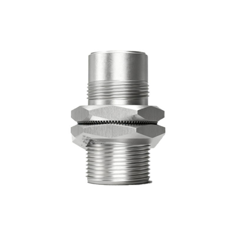
The core function of the sensor—detecting a target—must also be considered. The indicator light is often tied to the output state. For a normally open (NO) sensor, the light should turn on when a valid target is within the sensing range. If the light remains off, the target might be unsuitable. Ensure the target material, size, and approach speed meet the sensor's specifications. For instance, a mild steel target is ideal for standard inductive sensors, while stainless steel requires a reduced sensing distance. A target that is too small or moving too fast may not be detected reliably. Also, check for the presence of other metals or objects in the sensing field that could be causing interference or shielding.
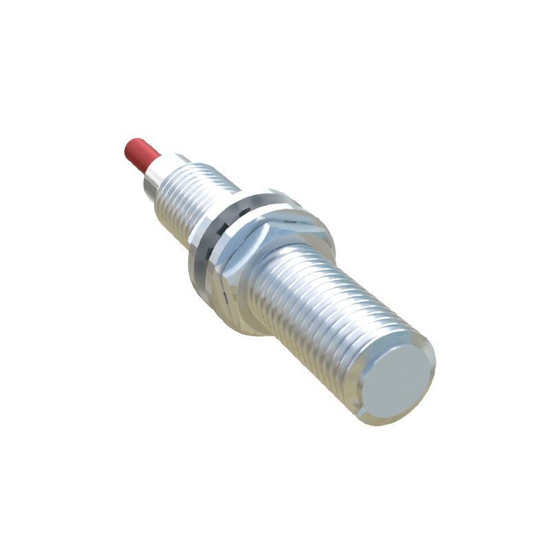
Internal component failure is a definitive possibility, especially in harsh operating conditions involving moisture, chemical exposure, or electrical transients. The LED itself can burn out. While a simple component, it is often integrated into a complex circuit. The oscillator circuit (in inductive sensors), the output switching element (transistor or relay), or associated resistors and capacitors can fail. Surges or voltage spikes on the supply lines are common culprits for such failures. If you have a known working sensor of the same model, a substitution test is one of the fastest ways to confirm a faulty unit. Before replacing, however, double-check the load connected to the sensor's output. A short circuit or an excessively high inrush current from the load (like a solenoid valve) can damage the sensor's output stage, which may also control the indicator light.
A logical troubleshooting flowchart is highly effective:
1. Power Check: Confirm correct voltage and polarity at the sensor terminals. Verify wiring integrity.
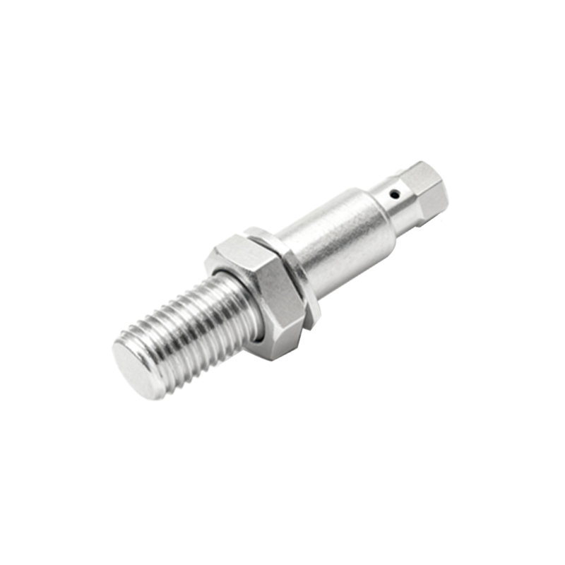
2. Target & Setup: Ensure a correct target is present within the rated sensing distance. Review any programming modes or timer settings.
3. Environment: Clean the sensor face. Check for temperature extremes, moisture ingress, or physical damage.
4. Load & Wiring: Disconnect the load and check for shorts. Measure the output signal directly.
5. Substitution: Swap the sensor with a verified working unit. If the new unit works, the original is faulty.
6. Diagnosis: If the new unit also fails, the problem lies in the power supply, wiring, or load in the circuit.
Preventive maintenance can reduce the occurrence of these issues. Regularly inspect sensors for physical damage and contamination. Ensure electrical connections are tight and protected from vibration. Use surge protection devices on supply lines in environments prone to electrical noise. Always follow the manufacturer's installation guidelines regarding sensing distances, mounting, and environmental ratings.
In conclusion, a proximity switch sensor with an unlit indicator light is a clear call for diagnostic action. The cause rarely lies with the LED alone but