In industrial automation and electrical engineering, precise proximity sensing is critical for operational safety, efficiency, and equipment longevity. The Hammer Nut PR2 series of inductive proximity sensors is widely employed in machinery, conveyor systems, and robotic cells for non-contact detection of metallic objects. Over time, factors such as mechanical vibration, thermal drift, electrical noise, and sensor aging can degrade detection accuracy. Regular and proper calibration is therefore not merely a recommendation but a fundamental maintenance procedure. This guide details the professional calibration process for the Hammer Nut PR2 proximity sensor, adhering to industry best practices.
Before initiating calibration, ensure a safe working environment. De-energize the control circuit and lock out/tag out (LOTO) the power source. Verify the sensor model (PR2-□□□) and its specifications from the datasheet, noting its nominal sensing distance (Sn), operating voltage range (typically 10-30V DC), output type (PNP/NPN, NO/NC), and housing material. Gather the necessary tools: a certified calibration test target (a square metal plate of standard thickness and side length, usually 1mm thick ferrous steel with side length equal to the sensor diameter), a precision distance gauge or set of feeler gauges, a stable DC power supply, a digital multimeter, and appropriate hand tools.
The calibration procedure follows a systematic approach. First, perform a visual and mechanical inspection. Check the sensor housing for cracks, corrosion, or physical damage. Ensure the sensing face is clean and free from debris, metal chips, or oil film that could interfere with the electromagnetic field. Confirm the mounting is secure and properly aligned; even a slight angular misalignment can significantly reduce the effective sensing distance.
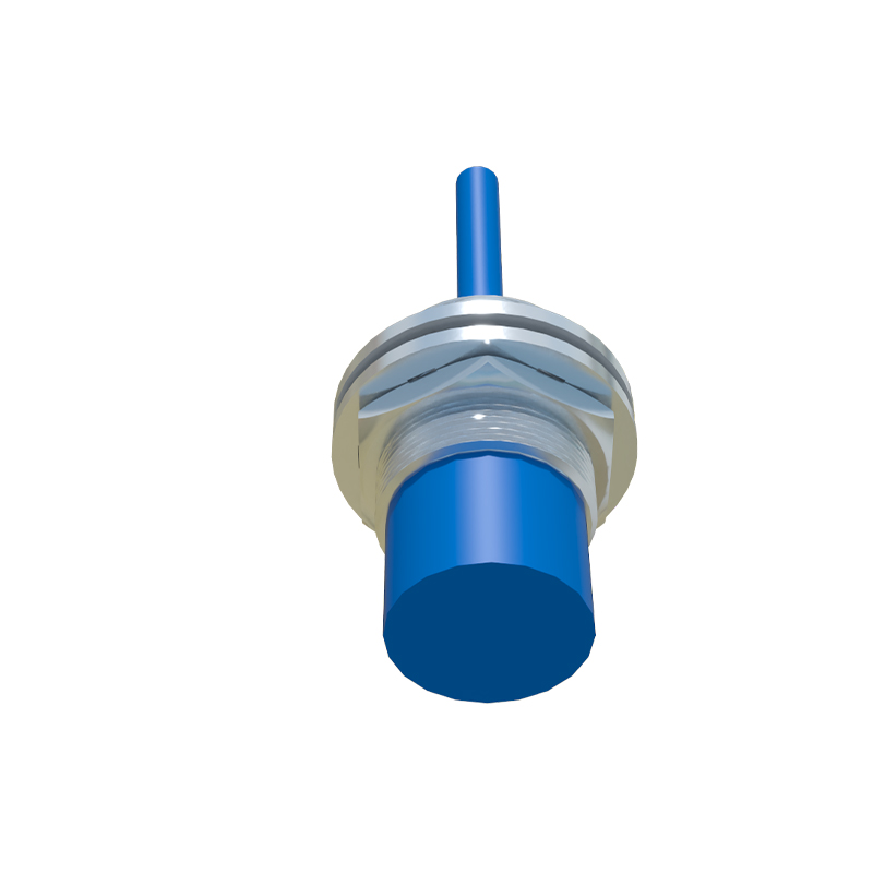
Next, establish the electrical connection. Wire the sensor according to its datasheet: connect the brown wire to the positive DC supply, the blue wire to the negative/ground, and the black wire (for PNP normally open type) to the load (e.g., a PLC input module or a multimeter for testing). Power on the system within the specified voltage range. The sensor's LED indicator should illuminate steadily, indicating power is present.
The core calibration involves measuring the actual sensing distance. Use the standard test target. Gradually move the target toward the sensor's sensing face along the axial centerline. The critical point is the "operating point"—the distance at which the sensor's output switches state (from OFF to ON for NO type). Use the distance gauge to measure this gap precisely when the LED changes state and the multimeter registers the output voltage switch. Record this value as the actual operating distance (Sa).
Compare the measured Sa with the sensor's nominal sensing distance (Sn). For most industrial applications, the acceptable tolerance is within ±10% of Sn. For instance, if a PR2 sensor has an Sn of 8mm, the Sa should be between 7.2mm and 8.8mm. If the Sa falls outside this range, adjustment is required.
Many Hammer Nut PR2 models feature a built-in potentiometer for sensitivity adjustment, often accessible via a small screw on the rear or side of the housing. Using a non-conductive trim tool, make minute adjustments. To increase the sensing distance (if Sa is too small), rotate the potentiometer counter-clockwise. To decrease the sensing distance (if Sa is too large), rotate it clockwise. After each adjustment, repeat the target approach measurement to obtain a new Sa value. Proceed incrementally; large, sudden adjustments can lead to overshoot and unstable switching behavior.
Once the Sa is within the desired tolerance, perform a hysteresis check. This involves finding the "release point"—the distance at which the output switches back to its original state as the target moves away. The difference between the operating point and the release point is the hysteresis, which is a designed characteristic to prevent output chatter. Ensure this hysteresis value is stable and consistent.
Finally, conduct a reliability test. Perform at least 50 approach-and-retract cycles at the calibrated distance to ensure consistent switching without false triggers or failures. Monitor the output signal on an oscilloscope if possible to check for clean switching edges without excessive noise. Also, test under simulated operational conditions, considering the effects of different target materials (if applicable) and the presence of nearby metal objects that could cause shielding or interference.
Document all findings: sensor identification, initial Sa, final calibrated Sa, adjustment steps, hysteresis value, and test results. This record is vital for predictive maintenance and audit trails. Regular calibration intervals should be established based on the operating environment's severity, typically every 6 to 12 months.
In summary, meticulous calibration of the Hammer Nut PR2 proximity sensor ensures reliable performance, minimizes downtime, and safeguards automated processes. By following this standardized procedure, engineers and technicians can maintain optimal sensing accuracy, contributing to the overall