In the textile manufacturing industry, circular knitting machines represent a significant capital investment, and their operational efficiency directly impacts productivity and fabric quality. A critical component for ensuring smooth, high-speed operation is the rotational speed monitoring system, which relies heavily on the precise function of proximity switch sensors. These non-contact sensors detect the presence or absence of a metallic target, typically a key or bolt on the machine's main drive shaft or cylinder, to provide real-time RPM data to the control system. The accuracy of this data is paramount, and it is fundamentally determined by one factor: the sensor's installation position.
The primary function of the proximity sensor in this context is to generate a clean, consistent pulse for each revolution of the machine. This pulse train is the input for the PLC or dedicated speed controller, enabling functions like speed display, production counting, overspeed/underspeed alarms, and synchronization with other machine sections. An incorrectly positioned sensor leads to erratic pulse generation, causing faulty readings, potential machine stoppages, or even undetected operational issues that degrade product quality over time.
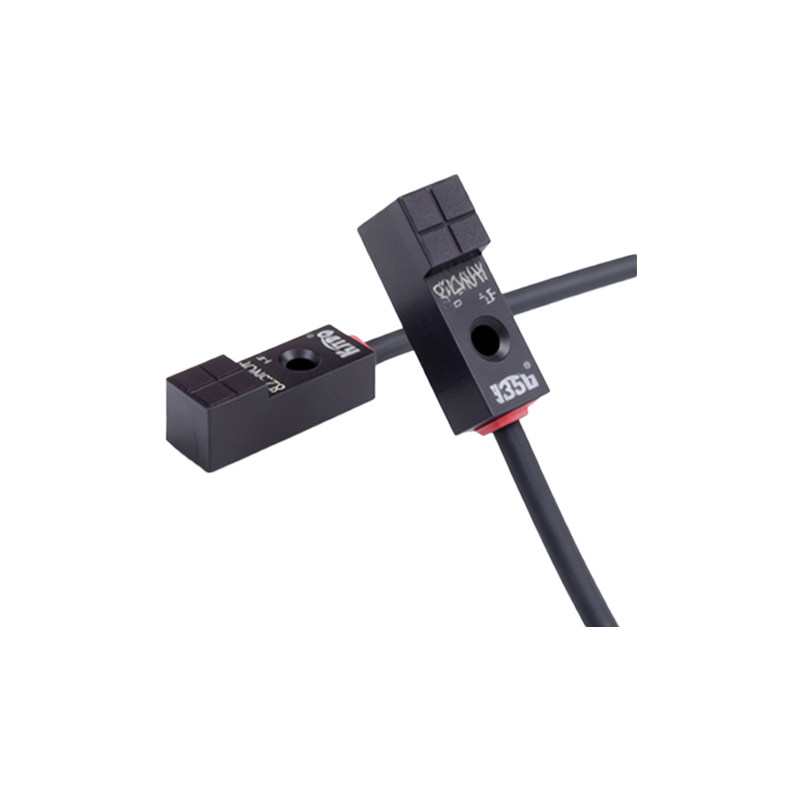
The optimal positioning strategy involves a systematic approach. First, identify a suitable metallic target on the rotating element. This target must be securely fastened and have a flat surface area larger than the sensor's sensing face to ensure reliable detection. Common targets include a dedicated machined key, a bolt head, or a small steel plate welded onto the shaft flange. The target should be singular per revolution to avoid double-pulsing.
Second, and most crucially, is the mounting of the sensor itself. The sensor must be rigidly fixed to a stationary part of the machine frame using a proper bracket to eliminate any vibration-induced movement. The critical parameters are the axial gap and the radial alignment. The sensing face should be positioned directly opposite the center of the target's travel path. The axial gap—the distance between the sensor face and the target surface—must be set according to the sensor's specifications, usually between 1mm to 5mm for inductive proximity switches. This gap must account for any axial play or thermal expansion of the shaft; a common practice is to set it at 60-70% of the sensor's rated sensing distance to ensure a strong signal margin.
Radial alignment is equally important. The sensor should be aligned so the target passes directly across the center of its sensing face. Misalignment can cause the target to pass through the edge of the detection field, resulting in a weaker or inconsistent signal, especially at high rotational speeds. For optimal signal strength and immunity to electrical noise, the sensor should be positioned so that the target approaches the sensor perpendicularly, not at a glancing angle.
Environmental considerations are vital. The location should be chosen to minimize exposure to flying lint, oil mist, and coolant sprays, which can coat the sensor face and attenuate the signal. If unavoidable, a suitable protective shield or a sensor with a high IP rating (e.g., IP67) is recommended. Additionally, the sensor should be routed away from high-power cables, motor drives, and other sources of electromagnetic interference to prevent signal corruption.
Finally, after physical installation, verification is essential. Using an oscilloscope or a PLC input diagnostic tool, observe the generated pulse waveform. It should be a clean, square wave with sharp rising and falling edges, without bounce or noise. The pulse duration should be consistent from cycle to cycle. Any irregularity indicates a need to re-check the gap, alignment, or target integrity.
In summary, the performance of a circular knitting machine's speed monitoring system is not merely a function of sensor quality but is intrinsically tied to meticulous installation geometry. By adhering to principles of secure mounting, precise axial and radial positioning, environmental protection, and post-installation signal verification, engineers can ensure reliable pulse generation. This translates into accurate speed control, minimized unplanned downtime, consistent fabric quality, and protection of the mechanical drive system from harmful speed excursions. The sensor position, though a small detail, is a cornerstone of predictive maintenance and overall equipment effectiveness (OEE) in modern textile production.