Proximity sensors are essential components in industrial automation, providing non-contact detection of objects for precise control and monitoring. Integrating these sensors with Programmable Logic Controllers (PLCs) enables efficient machine operation, safety interlocks, and data acquisition. This guide outlines the fundamental steps and considerations for connecting proximity sensors to PLC control systems, adhering to industry standards and best practices.
Proximity sensors come in various types, including inductive, capacitive, and photoelectric sensors, each suited for specific applications. Inductive sensors detect metallic objects, capacitive sensors handle non-metallic materials, and photoelectric sensors use light beams for detection. Before connection, verify the sensor’s specifications—such as operating voltage (commonly 12-24V DC or 110-240V AC), output type (PNP or NPN for DC sensors), and sensing range—to ensure compatibility with the PLC’s input modules.
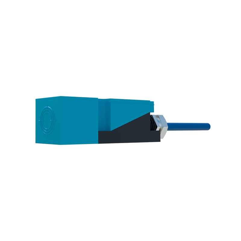
The connection process involves both hardware wiring and software configuration. For hardware, start by powering the sensor according to its voltage requirements. DC sensors typically have three wires: brown (positive), blue (negative), and black (output). Connect the brown wire to the DC positive supply, the blue wire to the DC negative or ground, and the black wire to the PLC’s digital input terminal. Ensure the PLC input module matches the sensor’s output type; PNP sensors (sourcing output) require sinking PLC inputs, while NPN sensors (sinking output) need sourcing PLC inputs. For AC sensors, connect the live and neutral wires to the power source, and link the output wire to the PLC input. Always use shielded cables and proper grounding to minimize electrical noise interference, which can cause false triggers.
In the PLC software, configure the input channel corresponding to the sensor’s connection. Assign a tag or address (e.g., I0.0 for Siemens PLCs or X0 for Mitsubishi PLCs) to the input, and program logic to respond to the sensor’s signal. For instance, a sensor detecting a part on a conveyor might trigger a timer or activate a robotic arm. Test the setup by simulating object detection and monitoring the PLC’s input status indicators. Adjust sensor sensitivity if needed, and implement diagnostics, such as alarm routines for sensor failures, to enhance system reliability.
Safety is paramount when connecting proximity sensors to PLCs. Follow lockout-tagout procedures during installation, and use safety relays or dual-channel connections for critical applications like emergency stops. Regularly inspect sensors for damage or contamination, and calibrate them as per manufacturer guidelines. By mastering these connections, engineers can optimize automation systems for improved productivity and reduced downtime.