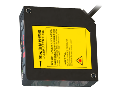
In industrial automation, laser sensors play a critical role in precision measurement, object detection, and quality control. Proper wiring and simulation of these sensors are essential to ensure system reliability, safety, and accuracy. This guide provides a comprehensive overview of laser sensor wiring principles and simulation techniques tailored for engineers and technicians in the electrical and automation fields.
Laser sensors typically operate on low-voltage DC power, commonly 12-24V DC, though some models may support wider ranges. The wiring process begins with identifying the sensor's pin configuration, which usually includes power supply terminals (V+ and V-), output signals (such as NPN or PNP transistor outputs), and sometimes auxiliary communication lines for advanced models. Always refer to the manufacturer's datasheet for specific pin assignments and voltage tolerances. For power connections, use shielded cables to minimize electromagnetic interference (EMI), and ensure proper grounding to prevent noise from affecting signal integrity. The output wiring depends on the sensor type: NPN (sinking) outputs connect the load to the positive supply, while PNP (sourcing) outputs connect it to ground. Mismatching these can lead to circuit damage or malfunction.
When integrating laser sensors into a control system, such as a PLC (Programmable Logic Controller) or microcontroller, careful attention must be paid to signal compatibility. For instance, if a sensor has an NPN output, it may require a pull-up resistor when interfacing with a PLC digital input to ensure a clear logic high state. Additionally, for long-distance wiring—beyond 50 meters—consider using signal amplifiers or repeaters to prevent voltage drop and signal degradation. Always follow industry standards like IEC 61131 for electrical installations and use conduit or cable trays to protect wires from physical damage and environmental factors like moisture or dust.

Simulation is a vital step in validating laser sensor performance before deployment. Engineers can use software tools such as MATLAB/Simulink, LabVIEW, or specialized PLC simulation environments to model sensor behavior. In simulation, key parameters to replicate include response time, sensing range, and output signal characteristics. For example, in Simulink, one can create a block diagram that mimics the sensor's analog or digital output based on input variables like distance or reflectivity. This allows for testing under various scenarios, such as detecting objects of different sizes or materials, without physical hardware. Simulation also helps in troubleshooting potential issues like signal delay or interference, enabling optimization of the sensor setup.
For advanced applications, such as integrating laser sensors with IoT systems or predictive maintenance algorithms, simulation can extend to network-level modeling. Tools like COMSOL Multiphysics can simulate electromagnetic wave propagation to assess how environmental factors affect laser accuracy. Additionally, using Python with libraries like NumPy and SciPy, engineers can script custom simulations to analyze data trends or calibrate sensors for specific tasks. Always cross-verify simulation results with real-world tests using oscilloscopes or multimeters to ensure alignment.
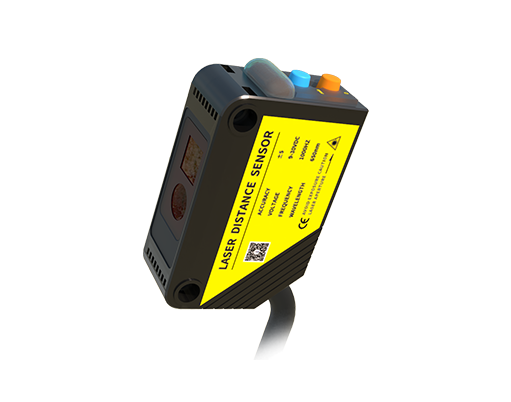
In summary, wiring laser sensors correctly involves adhering to power requirements, shielding against interference, and matching output types to control systems. Simulation complements this by providing a risk-free environment for testing and optimization. By mastering these practices, professionals can enhance system efficiency and reduce downtime in industrial settings. For further learning, consult resources like the IEEE standards on sensor integration or attend workshops on industrial automation technologies.