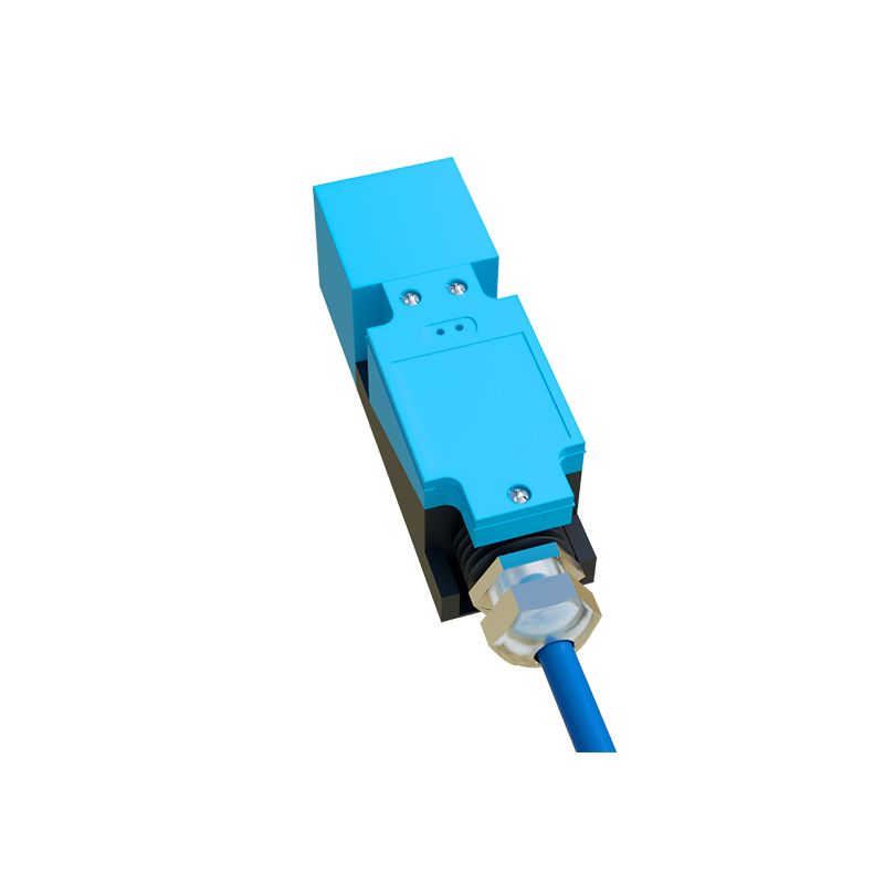
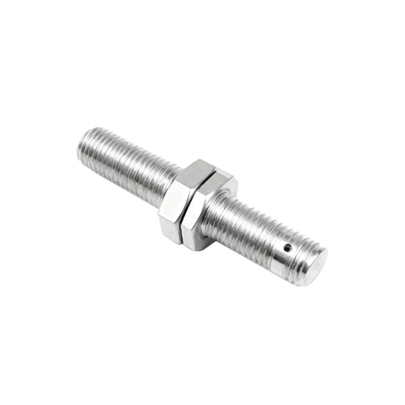
In industrial automation and control systems, proximity sensors and relays form a fundamental pairing for enabling efficient machine operation. A proximity sensor detects the presence or absence of an object without physical contact, typically outputting a digital signal. A relay, acting as an electrically operated switch, then uses this signal to control a higher-power circuit, such as a motor, solenoid, or lamp. Understanding the correct wiring diagram and implementation principles is crucial for reliability and safety.
The core of connecting a proximity sensor to a relay lies in interpreting the sensor's output type. The two most common configurations are PNP (sourcing) and NPN (sinking) transistor outputs. A PNP sensor switches the positive voltage to the load, while an NPN sensor switches the negative or ground path. The relay coil acts as the load. For a standard DC sensor, a three-wire design is typical: brown wire for DC positive (+V), blue wire for DC negative (0V or common), and black wire as the switched output signal.
A classic wiring diagram for a PNP proximity sensor to a relay is as follows:
1. Connect the sensor's brown wire to the positive terminal of the DC power supply (e.g., +24V).
2. Connect the sensor's blue wire to the negative terminal (0V) of the same DC supply.
3. Connect the sensor's black (output) wire to one terminal of the relay coil.
4. Connect the other terminal of the relay coil directly to the power supply's 0V (negative).
In this configuration, when the sensor detects a target, its output transistor activates, sourcing +24V from the brown wire through the black wire to the relay coil. The current flows through the coil to 0V, energizing the relay and closing its contacts to switch the external load circuit.

For an NPN proximity sensor, the wiring differs:
1. The brown and blue wires connect to +V and 0V as before.
2. Connect one terminal of the relay coil to the positive supply (+V).
3. Connect the sensor's black (output) wire to the other terminal of the relay coil.
4. There is no direct connection from the coil to 0V here. Instead, when the NPN sensor activates, it switches the black wire to 0V, completing the circuit from +V, through the coil, through the sensor's output transistor to 0V, thus energizing the relay.
Critical considerations include:
- Power Supply Compatibility: Ensure the sensor and relay coil voltage ratings match the supply (commonly 12V DC or 24V DC).
- Flyback Diode: Always install a diode (like 1N4007) in reverse bias across the relay coil terminals to suppress voltage spikes from coil de-energization, protecting the sensor's output transistor.
- Current Draw: Verify the sensor's maximum output current is not exceeded by the relay coil's inrush and holding current. Use an intermediate relay if the coil current is too high.
- Shielded Cabling: In electrically noisy environments, use shielded cables for sensor wiring, grounding the shield at one end to prevent false triggering.
- Load Connection: The relay's switched contacts (normally open or normally closed) are then wired to the final load (e.g., motor starter) with appropriate overload protection.
Practical applications are vast. On a conveyor line, a capacitive proximity sensor detecting a metal container can trigger a relay to activate a diverter arm. In a safety interlock system, an inductive sensor confirming a guard door is closed can enable a relay circuit allowing machine start. For diagnostic purposes, an LED indicator can be wired in parallel with the relay coil for visual status.
Troubleshooting often involves checking power at the sensor, verifying output activation with a multimeter, and ensuring the relay coil resistance is within specification. Remember, a solid-state proximity sensor requires a minimum load current to function correctly; some models may need a "bleeder" resistor if the relay coil draw is too low.
By mastering this fundamental interface, engineers and technicians can design robust, maintainable control logic, forming the backbone of automated systems. Always consult the specific manufacturer's datasheets for absolute pinouts and specifications, as colors and terminal designations can vary.