In industrial automation and control systems, proximity sensors are critical components for non-contact object detection. A common yet perplexing issue encountered by maintenance engineers and technicians is when a proximity sensor appears to be functioning—it has a confirmed output signal—but its built-in indicator light fails to illuminate. This discrepancy can lead to confusion during diagnostics, as the indicator light is often the primary visual cue for operational status. Understanding the root causes and systematic troubleshooting steps is essential for efficient resolution and minimal downtime.
Firstly, it is crucial to verify the fundamental operation. A proximity sensor generating a valid output signal (e.g., switching a load, providing a PLC input) is, in essence, performing its core function. The indicator light is a separate, parallel circuit designed for human interface. Therefore, the problem often lies not in the sensing element or the main switching output, but specifically within the indicator circuit. Begin by confirming the signal's presence using a multimeter to check the voltage at the output terminals or by verifying the PLC input status. Once the output signal is confirmed, the focus shifts exclusively to the indicator subsystem.
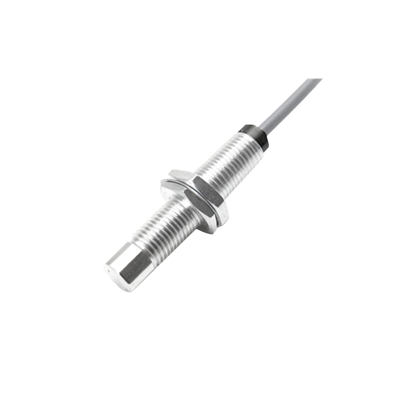
The most frequent cause is a failed LED. The light-emitting diode (LED) itself has a finite lifespan, though typically very long. It can fail due to manufacturing defects, excessive current from voltage spikes or incorrect wiring, or simply age. In many sensor designs, the LED is in series with a current-limiting resistor. If the LED fails open, the circuit is broken, and no light is emitted, even if the switching transistor is active. Diagnosing this often requires checking the voltage across the LED terminals when the sensor is in the active state. A voltage drop present where there should be none (indicating an open circuit) points to a failed LED or a broken solder joint on its connections.
Another common culprit is a problem with the current-limiting resistor or associated circuitry protecting the LED. This resistor can burn out due to a transient overvoltage event, such as from inductive load switching on the same power line or electrostatic discharge. In some three-wire DC sensors, the indicator circuit might be powered through a different internal path. A failed resistor or a damaged diode in this path will stop current from reaching the LED. Inspecting the sensor's schematic, if available, is invaluable here. Without a schematic, comparative resistance measurements against a known-good sensor of the same model can sometimes reveal anomalies.
Wiring and power supply issues, while less likely if the main output is working, should not be entirely dismissed. For AC sensors, the indicator might be on the load side. If the load is malfunctioning or not drawing current, the sensor might switch, but the LED path remains incomplete. Ensure the load is operational and correctly connected. For DC sensors, verify that the supply voltage is within the sensor's specified range, both for the main circuit and, if separately specified, for the indicator. Voltage at the extremes of the tolerance band might barely power the output transistor but be insufficient for the LED.
Environmental factors can also play a role. Contamination inside the sensor housing, such as conductive dust or moisture, can create a partial short or high-resistance path that diverts current away from the LED. Physical damage from vibration or impact can cause internal wire bonds to break, specifically affecting the indicator circuit. A thorough visual inspection of the sensor's interior, if it is a serviceable model, can reveal such issues.
The design of the sensor itself is a key consideration. Some proximity sensors feature a programmable or configurable indicator. Through a teach-in procedure or a configuration tool, the LED behavior can be set to "always off," "on for output active," "on for output inactive," or a blinking pattern for diagnostics. It is entirely possible the sensor is operating correctly, but the indicator mode has been inadvertently changed. Consult the manufacturer's datasheet to understand configurable features and how to reset or reprogram the LED function.
Finally, consider the possibility of an incorrect sensor model or substitution. Different models from the same manufacturer may have identical housings and connectors but different internal wiring schemes for the indicator. A sensor designed for a sinking (NPN) output configuration might wire its LED differently than one for a sourcing (PNP) output. Installing a sensor not exactly matched to the original specifications can result in this signal-without-light scenario.
Troubleshooting should follow a logical sequence: Confirm the output signal independently of the light. Review sensor documentation for configurability. Inspect for physical and environmental damage. Perform electrical measurements on the indicator circuit if possible. As a field expedient, if the output signal is verified and critical for operation, the sensor can often remain in service despite the dead LED, though this reduces diagnostic capability for future issues. The definitive repair, given the integrated nature of most modern proximity sensors, is typically replacement of the unit. However, a precise