In the realm of industrial automation and electrical engineering, proximity sensors are indispensable components for detecting the presence or absence of an object without physical contact. A common point of inquiry, especially for those new to sensor integration, revolves around the wiring: what is the cable or wire connected to a proximity sensor called? The answer, while seemingly straightforward, opens the door to a deeper understanding of sensor installation, selection, and functionality. This article delves into the terminology, types, and critical considerations surrounding the wiring of proximity sensors.
Firstly, the cable assembly connected to a proximity sensor is most accurately and commonly referred to as the sensor cable, proximity sensor cable, or interconnect cable. In more technical procurement or specification documents, you might encounter terms like pre-wired cable, integrated cable, or connector cable assembly. The specific name can depend on the sensor's design. Some sensors come with a fixed, permanently attached cable (often called a pigtail or hard-wired version), while others feature a quick-disconnect system where a separate cable, often termed a connector cable or mating cable, plugs into a built-in sensor connector.
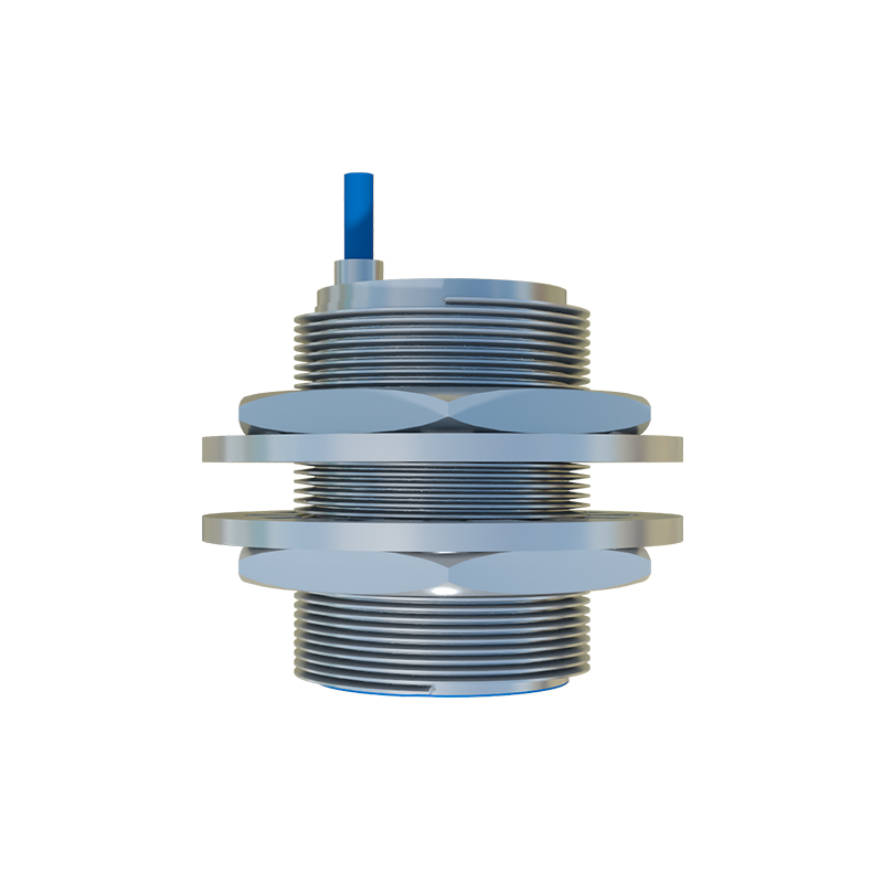
Understanding the wiring goes beyond mere nomenclature; it is fundamentally about the electrical connection that enables the sensor to operate and communicate with a control system like a PLC (Programmable Logic Controller). A standard proximity sensor cable typically contains two, three, or four conductors, insulated and bundled within an outer jacket. The number of wires corresponds to the sensor's output type and wiring scheme.
The most prevalent types are 2-wire, 3-wire, and 4-wire DC sensors. A 2-wire sensor is wired in series with the load; one wire connects to the positive DC supply, and the other acts as the switched output to the load. It simplifies installation but requires careful consideration of voltage drop. The 3-wire sensor is the industry workhorse, offering separate wires for power supply positive, power supply negative (common), and the output signal (either PNP or NPN sourcing). This design provides more stable performance and easier troubleshooting. 4-wire sensors typically incorporate two separate outputs (e.g., one normally open and one normally closed) or, in some cases, a complementary output pair alongside power wires.
The cable's construction is critical for industrial durability. Key specifications include:
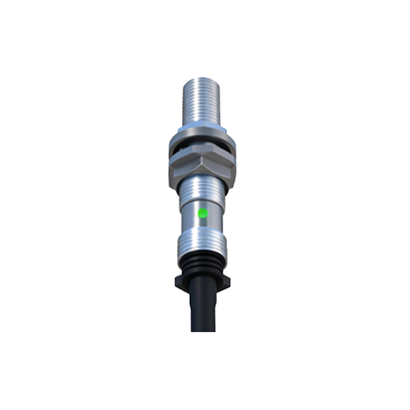
Conductor: Usually stranded copper for flexibility.
Insulation: Materials like PVC, PUR, or TPE offer varying degrees of resistance to oil, chemicals, abrasion, and temperature extremes. PUR cables are renowned for high flexibility and durability in harsh environments.
Shielding: A braided or foil shield is often included to protect the signal from electromagnetic interference (EMI), which is crucial in environments with motors, drives, and welding equipment.
Jacket Color: Standard colors like black or brown are common, but specific colors might indicate oil resistance or other properties.
Connector: If applicable, common connector styles include M8, M12 (3-pin, 4-pin), or M23 circular connectors, with coding keys (A-coded for sensors, B-coded for fieldbus, etc.) to prevent mismating.
Selecting the correct cable is not an afterthought. An improper cable can lead to sensor malfunction, intermittent operation, or premature failure. Engineers must match the cable's electrical ratings (voltage, current) with the sensor and supply, ensure the connector type and pinout are correct, and verify that the jacket material is suitable for the installation environment—be it exposure to UV light, coolants, or continuous flexing in cable carrier applications.
Installation best practices emphasize proper cable routing, away from high-power lines to minimize noise coupling. Strain relief, either built into the sensor housing or added via cable glands, is essential to prevent tension from being transferred to the electrical terminations. For sensors with separate connectors, ensuring a secure, clean, and tight connection is paramount to maintain IP (Ingress Protection) ratings.
In conclusion, the wire connecting to a proximity sensor is simply but importantly called a sensor cable or interconnect cable. Its technical significance, however, is profound. It is the lifeline that carries power and signal, and its characteristics—conductor count, shielding, jacket material, and connector type—are integral to the sensor's reliability and longevity in an automated system. A seasoned engineer recognizes that specifying and installing the right cable is as crucial as selecting the sensor itself, ensuring robust performance in the demanding landscape of industrial electrical systems.