In industrial automation and control systems, proximity sensors are indispensable components for detecting the presence or absence of objects without physical contact. Among various types, 4-wire proximity sensors are widely favored for their versatility, offering both normally open (NO) and normally closed (NC) output configurations in a single device. This guide provides a comprehensive overview of the wiring principles, configurations, and best practices for 4-wire proximity sensors, ensuring reliable operation in diverse applications.
A standard 4-wire proximity sensor typically includes two wires for power supply and two for output signals. The power wires connect to a direct current (DC) source, commonly 10-30 VDC, which energizes the sensor's internal circuitry. The output wires provide a switched signal based on the detected object: one wire corresponds to the NO contact, and the other to the NC contact. This dual-output design allows flexibility in control logic, enabling users to select the appropriate output mode for their specific system requirements.
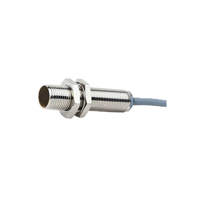
To wire a 4-wire proximity sensor correctly, follow these steps. First, identify the wire colors or markings as per the manufacturer's datasheet. Typically, brown (or red) denotes the positive power supply (+V), blue (or black) indicates the negative or ground (0V), black (or white) represents the NO output, and white (or gray) signifies the NC output. Always refer to the sensor's documentation to confirm these assignments, as variations may exist. Connect the brown wire to the positive terminal of the DC power source and the blue wire to the negative terminal. Ensure the voltage matches the sensor's rated range to prevent damage.
Next, integrate the output wires into the control circuit. For the NO output, connect the black wire to the input of a programmable logic controller (PLC), relay, or other control device. When an object enters the sensor's detection range, this circuit closes, sending a signal to the control system. Conversely, the white wire for the NC output should be connected similarly; it remains closed when no object is detected and opens upon detection. This configuration is useful for fail-safe applications, where a broken wire or power loss triggers an alarm.
Considerations for wiring include proper shielding and grounding to minimize electrical noise, especially in environments with motors or variable frequency drives. Use twisted-pair cables for the output signals and keep sensor cables away from high-voltage lines. Additionally, install surge suppressors if the sensor is connected to inductive loads like solenoids, as voltage spikes can shorten the sensor's lifespan. Always adhere to local electrical codes and safety standards during installation.
Testing the wired sensor is crucial for validation. Apply power and observe the sensor's indicator LED, which usually lights up when operational. Use a non-metallic object (for capacitive sensors) or a metal target (for inductive sensors) to trigger detection, and verify the output signal with a multimeter or PLC input status. If issues arise, double-check connections, power supply stability, and sensor alignment. Regular maintenance, such as cleaning the sensing face and inspecting cables for wear, ensures long-term reliability.
In summary, wiring a 4-wire proximity sensor involves connecting power and output wires accurately while considering environmental factors. By following this guide, engineers and technicians can optimize sensor performance, enhance system safety, and reduce downtime in industrial settings. For specific applications, consult the sensor's manual or seek expert advice to tailor the setup.