In industrial automation and electrical systems, proximity sensors are indispensable components for detecting the presence or absence of objects without physical contact. A common, yet often perplexing, phenomenon encountered by engineers and technicians is the blinking or flickering of the indicator light on these sensors. This blinking is not merely a random occurrence; it is a deliberate diagnostic language that communicates the sensor's operational status and potential issues within the circuit or its environment. Understanding this behavior is crucial for efficient troubleshooting and maintaining system integrity.
Fundamentally, the indicator light on a proximity sensor serves a dual purpose: to confirm power supply and to signal the detection state. A steady light typically indicates that the sensor is powered and, depending on its configuration (Normally Open or Normally Closed), either in a detecting or idle state. Blinking, however, introduces a layer of coded information. The most frequent cause of a blinking light is an output overload or a short-circuit condition. When the sensor's switching element (transistor or relay) attempts to drive a load that exceeds its rated current capacity, internal protection circuits activate. This protection often manifests as a rapid blinking of the LED, signaling that the output is being cycled on and off to prevent permanent damage from overheating. Engineers must immediately check the connected load—such as a solenoid valve, relay coil, or PLC input module—against the sensor's datasheet specifications for maximum current, ensuring proper sizing or adding an interposing relay if necessary.
Another prevalent cause is power supply instability. Proximity sensors, especially DC models, require a stable voltage within a specified range (e.g., 10-30 VDC). Voltage dips, ripple, or noise on the supply lines can cause the sensor's internal circuitry to reset or behave erratically, leading to a blinking indicator. This is common in environments with heavy inductive loads like large motors or welders, which can introduce significant electrical noise. Solutions involve verifying the supply voltage with a multimeter under load, implementing dedicated, regulated power supplies for sensitive sensors, and employing noise suppression techniques. These techniques include using shielded cables, ensuring proper grounding (earthing), and installing ferrite cores or RC snubber circuits across inductive loads.
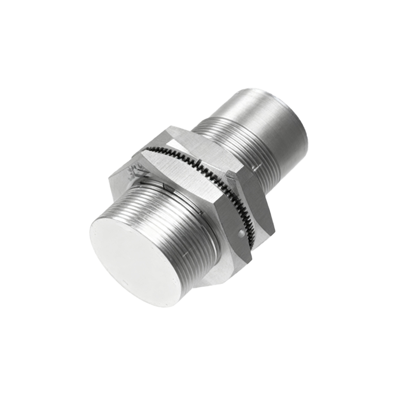
Wiring errors constitute a third major category. Incorrect polarity for DC sensors, loose connections, or damaged cables can create intermittent connections. A loose wire in the supply or load circuit might cause the sensor to momentarily lose power or the output to flutter, resulting in a blinking light. Meticulously inspecting the wiring against the manufacturer's diagram—paying close attention to the brown (L+), blue (L-), black (output), and white (complementary output) wire conventions—is essential. The integrity of the cable over its entire run, especially in areas with high vibration or mechanical stress, should also be examined.
Environmental interference can also trigger blinking. While proximity sensors are designed to be robust, extreme conditions can affect performance. Strong external electromagnetic fields (EMF) from nearby frequency drives or radio transmitters can induce false signals. Additionally, the accumulation of metallic dust or chips on the sensing face of an inductive sensor can alter its sensing characteristics, potentially causing the output to chatter and the light to blink. Regular maintenance to keep the sensing face clean and ensuring adequate physical separation from high-noise sources are effective countermeasures.
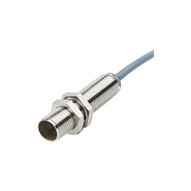
Finally, the blinking pattern itself can be a diagnostic tool. Some advanced sensor models feature programmable blink codes. A specific number of flashes followed by a pause can indicate precise faults like a sensor head alignment error, internal temperature warning, or a teach-mode activation. Consulting the specific product manual is imperative to decode these patterns accurately. In simpler two-wire AC sensors, a blinking light might simply indicate that the leakage current through the sensor in its "off" state is sufficient to weakly illuminate the LED, which is often normal but can be mistaken for a fault.
In conclusion, a blinking light on a proximity sensor is a critical communication from the device. It should never be ignored. The systematic approach to diagnosis starts with reviewing the simplest possibilities: verify the electrical load, inspect the power supply quality, and confirm all wiring. Cross-reference the observed behavior with the manufacturer's documentation. By interpreting this visual signal correctly, engineers can swiftly move from symptom to root cause, implementing targeted solutions that restore reliable operation and prevent costly downtime in automated systems.