In the realm of industrial automation and machine control, proximity sensors are indispensable components for non-contact object detection. Among the various types available, the 3-wire DC proximity sensor is arguably the most common and versatile. Its reliable operation hinges on a correct and safe wiring connection. This guide provides a detailed, step-by-step explanation of how to properly wire a 3-wire proximity sensor, covering fundamental principles, standard configurations, and essential safety considerations.
First, it is crucial to understand the basic anatomy of a standard 3-wire DC sensor. Unlike 2-wire sensors that are wired in series with the load, 3-wire sensors have separate paths for power supply and output signal, offering superior performance and stability. The three wires are typically color-coded as follows: Brown (or Red) for the positive supply voltage (+V), Blue (or Black) for the common negative or 0V (GND), and Black (or White, Blue, sometimes Yellow) for the output signal line. It is absolutely imperative to consult the specific sensor's datasheet or manual, as color codes can vary by manufacturer and region. The sensor's housing is also clearly marked with its operating voltage range (e.g., 10-30V DC) and its output type.
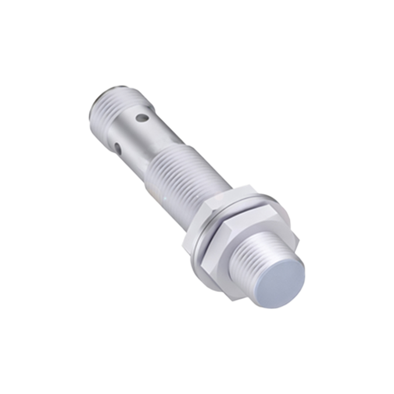
The output type is the single most important factor determining the wiring configuration. There are two primary types: NPN (Sinking) and PNP (Sourcing). This designation refers to the type of transistor used in the sensor's output stage and dictates the electrical path of the output current.
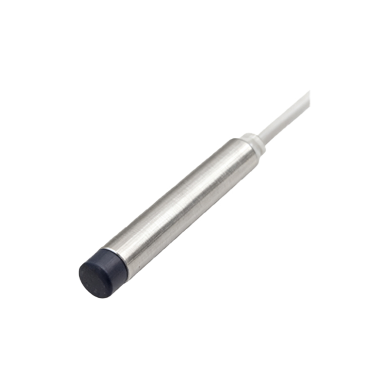
Wiring a PNP (Sourcing) Proximity Sensor:
A PNP sensor "sources" current. When the sensor is activated (detects a target), it connects the output signal line to the positive supply voltage. The standard wiring procedure is:
1. Connect the Brown wire to the positive terminal of your DC power supply (e.g., +24V).
2. Connect the Blue wire to the negative terminal (0V or GND) of the same DC power supply.
3. Connect the Black (output) wire to one terminal of your load (e.g., a PLC input, relay coil, or indicator lamp).
4. Connect the other terminal of your load back to the negative terminal (0V or GND) of the power supply.
In this configuration, when the sensor activates, positive voltage is "sourced" from the sensor's output wire, through the load, and back to ground, completing the circuit.
Wiring an NPN (Sinking) Proximity Sensor:
An NPN sensor "sinks" current. When activated, it connects the output signal line to the negative supply voltage (0V). The standard wiring is:
1. Connect the Brown wire to the positive terminal of your DC power supply (+V).
2. Connect the Blue wire to the negative terminal (0V) of the power supply.
3. Connect the Black (output) wire to one terminal of your load.
4. Connect the other terminal of your load back to the positive terminal of the power supply.
Here, when the sensor activates, it provides a path to ground (0V), allowing current to flow from the positive supply, through the load, and "sinked" into the sensor's output to ground.
Choosing between PNP and NPN often depends on the control system's input card configuration. Many PLCs in Europe and Asia are designed for PNP inputs, while NPN is common in some other regions. Always verify compatibility.
Critical Safety and Best Practices:
1. Power Off: Always disconnect power before making or modifying any electrical connections.
2. Verify Specifications: Double-check the sensor's voltage rating, output type, and wire colors against its documentation.
3. Use Correct Tools: Employ proper crimping tools for wire ferrules or terminals to ensure secure, vibration-resistant connections.
4. Shielded Cable: For environments with significant electrical noise (e.g., near VFDs or welding equipment), use shielded cable. Connect the cable shield to a proper earth ground at the control panel end only, leaving it unconnected at the sensor end to prevent ground loops.
5. Fusing: Protect the circuit with a fast-acting fuse of an appropriate rating, typically placed on the positive supply line.
6. Polarity Protection: While many modern sensors have reverse polarity protection, incorrect wiring can still cause permanent damage. Connect power correctly.
7. Load Considerations: Ensure the sensor's maximum output current rating is not exceeded by the connected load. For inductive loads like relay coils, use a flyback diode to suppress voltage spikes.
8. Testing: After