In the realm of industrial automation and machine safety, proximity switch sensors are ubiquitous, serving as the silent sentinels for object detection without physical contact. This teardown analysis provides a detailed visual and technical examination of a standard inductive proximity sensor, offering engineers and technicians a deeper understanding of its internal architecture, component selection, and operational principles.
Our subject is a typical cylindrical, shielded, DC-powered inductive proximity switch rated for 10-30V DC with a PNP normally-open output. The external housing is constructed from nickel-plated brass, providing robust electromagnetic shielding and mechanical durability. The sensing face is a high-grade, wear-resistant phenolic resin.
Initial Disassembly and External Housing
The disassembly begins by removing the plastic cable gland and strain relief assembly. The main cylindrical body unscrews, revealing a critical internal seal—a black nitrile O-ring—that ensures an IP67 ingress protection rating. The brass housing threads are precisely machined, and the interior is potted with a dark gray, semi-flexible polyurethane compound. This potting material is crucial for vibration damping, heat dissipation, and protecting the internal electronics from moisture and contaminants.
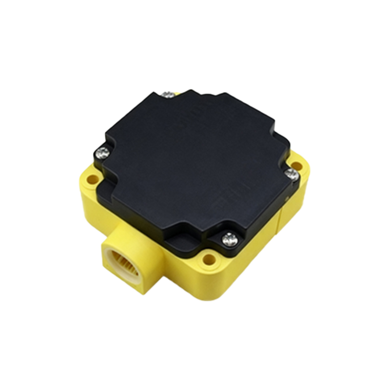
Core Electronics Assembly Revealed
Once the potting compound is carefully removed, the core printed circuit board (PCB) assembly is extracted. The PCB is a single-sided, glass-epoxy board. The components are wave-soldered, showing high-quality manufacturing standards. The layout is compact and logical, with clear segregation between the power section, oscillator circuit, detection circuit, and output stage.
Key Component Analysis:
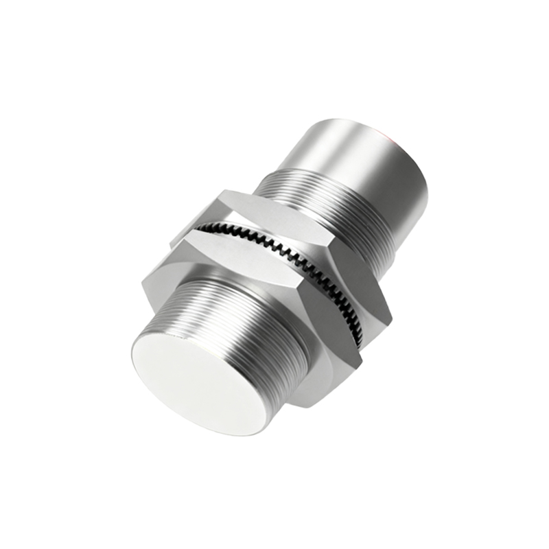
1. Oscillator Coil: The heart of the inductive sensor is a flat, spiral-wound copper coil fixed to the back of the sensing face. It is part of a high-frequency LC oscillator circuit. When a metallic object enters the sensor's magnetic field, eddy currents are induced in the object, causing a dampening of the oscillator's amplitude.
2. Ferrite Core: A small, ring-shaped ferrite core surrounds the coil's connection points, concentrating the electromagnetic field towards the sensing face and enhancing sensitivity and switching precision.
3. Microcontroller/ASIC: A small, black epoxy-blob integrated circuit serves as the dedicated Application-Specific Integrated Circuit (ASIC). This chip manages the oscillator, monitors amplitude change, provides hysteresis to prevent output chatter, and drives the output transistor. The use of an ASIC, rather than discrete components, explains the sensor's compact size and reliability.
4. Output Transistor: A surface-mount device (SMD) PNP transistor, rated for the sensor's current capacity (typically 200mA), is clearly visible. This transistor acts as the solid-state switch for the load (e.g., a PLC input).
5. Voltage Regulator & Protection Diodes: A small linear voltage regulator IC stabilizes the incoming supply voltage for the ASIC. Schottky diodes are present for reverse polarity protection and transient voltage suppression (TVS), safeguarding the circuit from wiring errors and voltage spikes common in industrial environments.
6. Status LED: An SMD LED, visible through a small light pipe in the housing, indicates power and output state.
Sensing Face and Magnetic Field Shielding
The shielded design is evident. The nickel-plated brass barrel extends slightly forward, forming a lip around the sensing face. This geometry focuses the electromagnetic field directly ahead, preventing lateral detection and allowing for flush mounting in metal. The internal potting compound also acts as a structural element, holding the coil assembly firmly in place against the sensing face.
Reassembly and Design Considerations
Reassembly confirms the thoughtful design for serviceability (though these units are typically sealed for life). The O-ring seal seats perfectly. The entire design prioritizes longevity and stability under thermal cycling and vibration.
Conclusion from the Teardown:
This proximity sensor exemplifies elegant, purpose-driven engineering. The design choices—from the shielded metal housing and high-quality potting to the dedicated ASIC and robust protection circuitry—are all directed towards achieving a singular goal: reliable, maintenance-free operation in harsh industrial settings. The internal construction reveals why these sensors can boast millions of operating cycles. For engineers, this teardown underscores the importance of component quality and mechanical design in achieving the reliability expected in industrial automation components. The images accompanying this analysis highlight the clean layout, quality soldering, and effective use of materials that contribute to the sensor's performance and durability.