Multifunctional proximity sensors are integral components in modern industrial automation, offering versatile detection capabilities without physical contact. Their structural design determines performance in diverse applications, from object detection to position sensing. This article provides a detailed breakdown of a typical multifunctional proximity sensor's structural diagram, highlighting key components and their functional roles.
The sensor's housing, typically constructed from robust materials like stainless steel or engineering plastics, serves as the primary protective shell. It shields internal electronics from environmental factors such as dust, moisture, and mechanical impact. The housing design often includes threaded or flanged mounting options for easy installation in industrial settings.
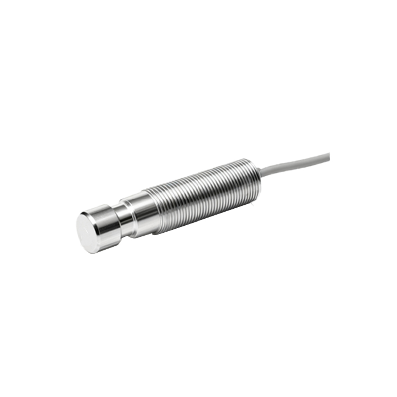
At the sensor's core lies the sensing element, which varies based on detection technology. Inductive sensors use a coiled oscillator circuit to generate an electromagnetic field, detecting metallic objects through eddy current losses. Capacitive sensors employ electrode plates to sense changes in capacitance caused by non-metallic materials. Photoelectric sensors integrate an LED light source and phototransistor receiver, utilizing light beam interruption or reflection for detection. Some advanced models combine multiple technologies into a single unit, enabling detection of various materials.
The oscillator circuit, a critical internal component, generates high-frequency signals for object detection. In inductive sensors, this circuit produces an oscillating magnetic field. When a metallic target enters this field, energy absorption dampens oscillations, triggering the output stage. The oscillator's frequency and amplitude are precisely calibrated to ensure consistent sensing ranges and minimize false triggers.
Signal processing electronics, including amplifiers, comparators, and microcontrollers, interpret raw sensor data. These components filter noise, adjust sensitivity thresholds, and convert analog signals into digital outputs. Modern sensors often incorporate programmable logic controllers (PLCs) interfaces, allowing customization of parameters like response time and output modes (e.g., NPN/PNP switching).
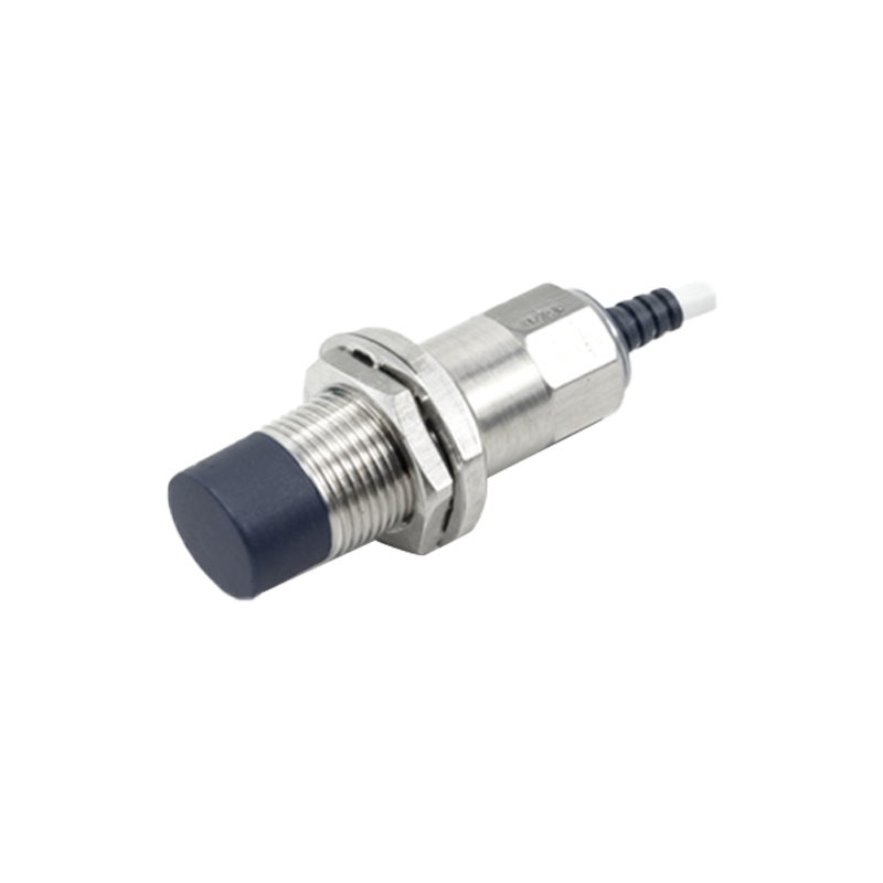
Output stages typically feature solid-state switches or relay contacts, providing electrical signals to control external devices. Common configurations include normally open (NO), normally closed (NC), or complementary outputs. Some sensors offer analog outputs (0-10V or 4-20mA) for continuous distance measurement, enhancing functionality in precision applications.
Wiring connections are facilitated through cable glands or connector ports, with color-coded leads for power supply, ground, and output signals. Standard voltage ranges include 10-30V DC or 90-250V AC, ensuring compatibility with industrial power systems. Advanced models incorporate diagnostic LEDs that indicate power status, target detection, and fault conditions, simplifying maintenance.
Environmental sealing, rated via IP (Ingress Protection) codes (e.g., IP67), prevents internal contamination. O-rings and epoxy resin encapsulation protect circuitry from liquids and particulate matter. Temperature compensation circuits maintain accuracy across operating ranges from -25°C to 70°C, crucial for harsh industrial environments.
In summary, the structural diagram of a multifunctional proximity sensor reveals a sophisticated integration of mechanical, electrical, and electronic components. Each element—from housing to output stage—is optimized for reliability, accuracy, and adaptability. Understanding this architecture aids in selecting appropriate sensors for specific applications, such as conveyor systems, robotic arms, or safety interlocks. As Industry 4.0 advances, these sensors continue evolving with features like IO-Link communication for real-time data exchange, further expanding their role in smart manufacturing ecosystems.