In the realm of industrial automation and electronic design, proximity sensor modules are fundamental components for non-contact detection. A common inquiry among engineers and technicians is: "What does a proximity sensor module schematic or circuit pattern look like?" This article delves into the typical circuit architecture and schematic patterns of these ubiquitous sensors, providing a clear technical overview.
At its core, a proximity sensor module schematic represents the electronic circuitry that enables the sensor to detect the presence or absence of an object within a specific range without physical contact. The pattern is not a single, universal diagram but a family of designs tailored to the underlying sensing technology. The most prevalent types are inductive, capacitive, and photoelectric proximity sensors, each with a distinct circuit pattern.
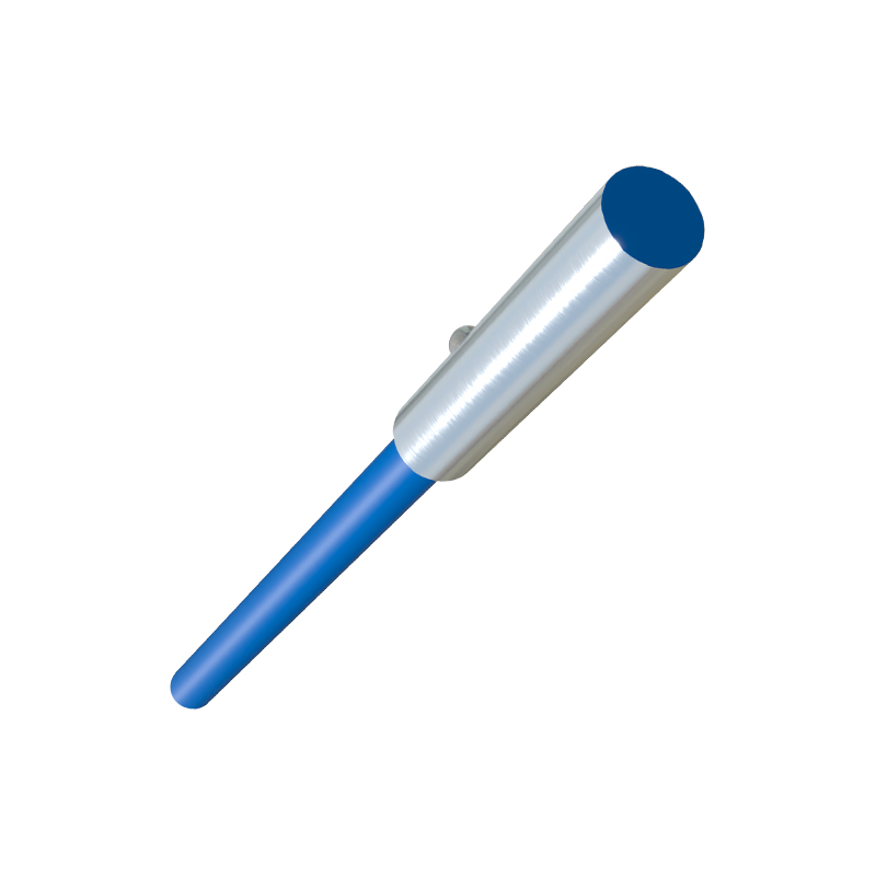
The schematic for a standard inductive proximity sensor module, designed to detect metallic objects, typically follows a clear pattern. It centers around an oscillator circuit, often a Colpitts or Hartley oscillator, which generates a high-frequency electromagnetic field from a coil (the sensor's sensing face). This oscillator is connected to a detection circuit. When a metal object enters the field, eddy currents are induced, causing a change in the oscillator's amplitude or frequency. This change is then fed into a trigger circuit (like a Schmitt trigger) which processes the signal and switches the output stage. The output stage usually consists of a transistor (NPN or PNP) in an open-collector configuration or a solid-state relay, providing a clean digital signal (e.g., 0V or 24V DC) to a programmable logic controller (PLC) or other control system. Protection components such as diodes for reverse polarity, capacitors for filtering, and sometimes a surge protection device are integral parts of the schematic pattern.
A capacitive proximity sensor module schematic shares similarities but is adapted to detect both metallic and non-metallic materials (plastics, liquids, etc.). Its pattern also features an oscillator, but the sensing element is a capacitor plate. The target object changes the dielectric constant or the capacitance of the circuit, altering the oscillator's condition. The subsequent trigger and output stages are conceptually similar to the inductive type. These schematics often include sensitivity adjustment components, such as a potentiometer, within the circuit pattern.
Photoelectric sensor modules (through-beam, retro-reflective, diffuse) present a different schematic pattern focused on optics and light conversion. The core components are an emitter (usually an LED, often infrared) driven by a constant current circuit and a receiver (phototransistor or photodiode). The receiver's circuit pattern includes amplification stages to boost the weak photocurrent and a comparator circuit to distinguish between light and dark states, ultimately driving the output transistor. These modules require precise current regulation for the emitter and often incorporate filters to reject ambient light interference.
Beyond the sensing core, a complete module schematic pattern always includes power supply conditioning. This involves voltage regulation (e.g., using a 78xx series regulator or a buck converter) and filtering to ensure stable operation amidst electrical noise common in industrial environments. The connection to the external world is represented by terminal blocks or connectors, clearly marked for power supply (Vcc and GND), output signal (OUT), and sometimes a shield wire.
Understanding this schematic pattern is crucial for several professional tasks: troubleshooting faulty sensors, integrating sensors into custom circuits, or designing application-specific sensing solutions. When examining a schematic, an engineer looks for the logical flow: Power Input -> Oscillator/Sensing Element -> Signal Conditioner/Trigger -> Output Driver -> Load. The specific values of resistors, capacitors, and inductor coils, along with the part numbers for ICs and transistors, define the sensor's characteristics like sensing distance, switching frequency, and output current capacity.
In summary, the "pattern" of a proximity sensor module schematic is a robust, standardized electronic layout that translates a physical phenomenon (presence of an object) into a reliable electrical signal. It is a marriage of analog signal generation/processing and digital switching, all designed for resilience and precision in demanding operational conditions. While the exact components vary by manufacturer and model, the fundamental architectural patterns—oscillator-based for inductive/capacitive and emitter-receiver for photoelectric—remain consistent, providing a reliable blueprint for functionality and diagnostics in the field of industrial electronics.