In industrial automation, proximity sensors play a critical role in detecting the presence or absence of objects without physical contact. Among these, the A59 series inductive proximity sensor is widely recognized for its robustness, reliability, and versatility in harsh environments. However, even the most advanced sensors require precise calibration to ensure accurate detection and long-term stability. This article provides a step-by-step guide to calibrating an A59 proximity sensor, covering essential principles, tools, and best practices for engineers and technicians.
Understanding the A59 proximity sensor’s operating principle is fundamental to effective calibration. As an inductive sensor, it generates an electromagnetic field from its active face. When a metallic target enters this field, eddy currents are induced, causing a change in the sensor’s oscillation amplitude. This change triggers the output switch. The A59 typically features a shielded design, allowing flush mounting in metal, and offers various output configurations (e.g., NPN/PNP, NO/NC). Key specifications include sensing range, repeat accuracy, hysteresis, and environmental ratings (IP67 or higher). Calibration ensures that the sensor operates within these specified parameters, minimizing false triggers and maximizing detection consistency.
Before beginning calibration, gather the necessary tools: a set of certified gauge blocks or test targets made of the sensor’s specified material (usually mild steel), a stable power supply matching the sensor’s voltage rating (e.g., 10-30V DC), a digital multimeter or oscilloscope for output verification, mounting fixtures, and personal protective equipment. Ensure the work area is clean, free from electromagnetic interference, and that the sensor is correctly installed per manufacturer guidelines—maintaining proper alignment, clearance from surrounding metal, and secure wiring.
The calibration process involves several methodical steps. First, power on the sensor and allow it to stabilize for at least five minutes, as temperature variations can affect performance. Using the gauge blocks, gradually bring the target toward the sensor’s active face. Monitor the output signal with your multimeter. The point at which the output switches (e.g., from 0V to 24V for a PNP sensor) is the actual sensing point. Compare this distance to the nominal sensing range specified in the datasheet. If a discrepancy exists, adjust the sensor’s potentiometer (if equipped) or reposition it mechanically. For sensors without adjustment features, fine-tune the mounting or target position.
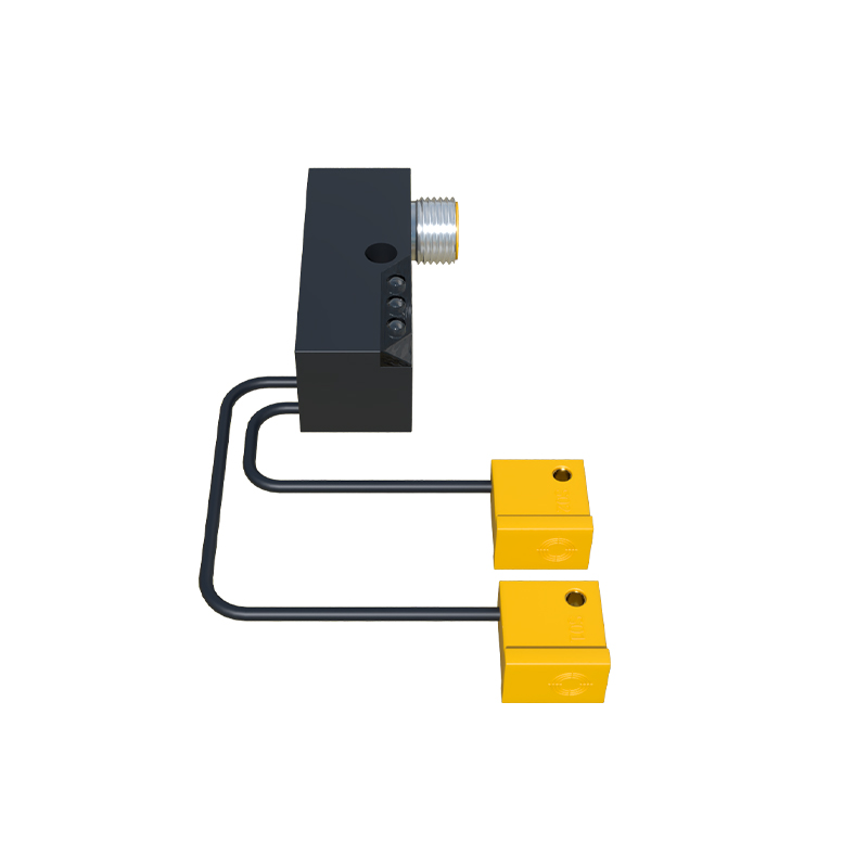
Repeatability testing is crucial. Perform at least ten approach-and-retract cycles with the target, recording the switch-on and switch-off points each time. Calculate the average sensing distance and the standard deviation to assess repeat accuracy. Hysteresis—the difference between the switch-on and switch-off points—should be within the datasheet limits (typically 3-15% of the sensing range). Excessive hysteresis may indicate sensor wear, target material issues, or electrical noise. Additionally, test under real-world conditions, such as with varying target sizes, speeds, and environmental factors like temperature shifts or vibration.
Common calibration challenges include sensing range drift due to temperature fluctuations, interference from adjacent sensors or motors, and target material variations. For temperature compensation, operate the sensor in its intended environment and allow thermal equilibrium. To mitigate electromagnetic interference, use shielded cables, proper grounding, and maintain adequate spacing between sensors. If detecting non-ferrous metals, note that the effective sensing range may be reduced; refer to correction factors in the manual. Always document calibration results, including date, conditions, and any adjustments made, for traceability and maintenance scheduling.
Regular maintenance extends sensor life. Periodically inspect the A59 for physical damage, contamination, or corrosion. Clean the active face with a soft cloth and isopropyl alcohol if needed. Recalibrate at intervals recommended by the manufacturer or based on operational criticality—typically every six to twelve months in demanding applications. For critical systems, consider implementing automated calibration routines using programmable logic controllers (PLCs) and feedback loops.
In summary, proper calibration of the A59 proximity sensor is not merely a one-time setup but an integral part of ensuring system reliability and efficiency. By adhering to systematic procedures, understanding sensor dynamics, and addressing environmental factors, engineers can optimize performance, reduce downtime, and enhance safety in automated processes. As technology evolves, integrating smart sensors with self-diagnostic features may simplify calibration, but the foundational principles outlined here remain essential for precision engineering.