In industrial automation and control systems, proximity sensors are indispensable components for non-contact object detection. The KNBG8-M12-NA is a widely used inductive proximity sensor known for its reliability, compact M12 housing, and normally open (NO) output configuration. Understanding its correct wiring is crucial for ensuring optimal performance, safety, and system integration. This guide provides a detailed overview of the KNBG8-M12-NA proximity sensor wiring diagram, following standard industry practices and electrical conventions.
The KNBG8-M12-NA typically features a 4-pin M12 quick-disconnect connector, which is standard for many industrial sensors. The pinout configuration is as follows:
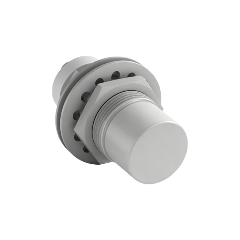
- Pin 1 (Brown Wire): This is the positive supply voltage terminal (+V). It must be connected to the positive DC power supply. The operating voltage range for this sensor is usually 10-30V DC, which should be verified against the specific model's datasheet.
- Pin 2 (Blue Wire): This is the negative supply voltage or ground terminal (0V). It must be connected to the common ground or negative side of the DC power supply.
- Pin 3 (Black Wire): This is the switched output signal line. As a normally open (NA or NO) sensor, this pin provides the output signal. When a metallic target enters the sensor's detection range, the internal switch closes, connecting Pin 3 to the load. In the inactive state (no target detected), this circuit remains open.
- Pin 4 (White Wire): This pin is often reserved for a complementary output or diagnostic function, depending on the manufacturer. For the standard 3-wire KNBG8-M12-NA configuration, Pin 4 may not be used or may be specified for an auxiliary function. It is critical to consult the official product manual, as some variants might use this pin for a normally closed (NC) output or a switching output of opposite logic.
A standard wiring diagram for connecting the KNBG8-M12-NA to a programmable logic controller (PLC) or a relay load involves the following steps:
1. Power Supply Connection: Connect the brown wire (Pin 1) to the positive terminal of a 24V DC power supply, which is common in industrial settings. Connect the blue wire (Pin 2) to the negative terminal of the same power supply. Ensure the power supply voltage matches the sensor's specifications to prevent damage.
2. Load Connection: Connect the black output wire (Pin 3) to one terminal of the load. The load could be a PLC digital input module, a relay coil, an indicator lamp, or another control device.
3. Completing the Load Circuit: Connect the other terminal of the load back to the positive side of the power supply (for PNP sourcing output type) or to the ground (for NPN sinking type). The KNBG8-M12-NA is typically a PNP (sourcing) sensor, meaning the black wire sources current to the load when activated. Therefore, the load's other terminal should be connected to ground (0V). For example: When a target is detected, the sensor internally connects Pin 3 (black) to the internal positive supply, providing a +24V signal to the PLC input. The PLC input common would be connected to ground.
4. Shield Connection (if applicable): If the sensor cable includes a shield or drain wire for electromagnetic interference (EMI) protection, it should be grounded at one end only, typically at the control panel side, to prevent ground loops.
Key considerations for installation and wiring include:
- Always de-energize the circuit before making connections to avoid electrical shock or short circuits.
- Use proper wire gauges suitable for the current rating of the sensor (usually below 200mA).
- Ensure correct polarity; reversing the brown and blue wires can permanently damage the sensor.
- Maintain proper cable routing, keeping sensor wires away from high-voltage power lines to minimize noise interference.
- For long cable runs, consider voltage drop and use shielded cables in electrically noisy environments.
- Verify the sensor's sensing distance and ensure the target material (ferrous or non-ferrous metal) is within specifications.
Troubleshooting common wiring issues often involves checking for:
- No Output Signal: Confirm power is present between brown (+V) and blue (0V) wires. Use a multimeter to check if the voltage at the sensor connector is within the specified range. Verify the target is within the sensing range and is of an appropriate material. Check if the load is functional by testing it with an alternative source.
- In