Line laser sensors, also known as line laser displacement sensors or profile sensors, are critical components in modern industrial automation, enabling high-precision measurement, inspection, and guidance. Proper calibration and debugging are essential to ensure their accuracy, reliability, and longevity in demanding environments such as automotive assembly, electronics manufacturing, and logistics. This guide outlines a systematic approach to setting up and troubleshooting these sensors, combining theoretical principles with hands-on engineering practices.
The initial phase involves mechanical and optical alignment. Mount the sensor securely on a stable bracket or fixture, minimizing vibrations that can distort the laser line. The sensor’s orientation relative to the target surface is paramount; the laser plane should be perpendicular to the primary measurement direction. Use precision levels and alignment jigs to achieve this. Adjust the standoff distance—the gap between the sensor head and the target—as specified in the datasheet. Even minor deviations can cause significant measurement errors. For triangulation-based sensors, the angle between the laser emitter and the receiver (CMOS/CCD) is fixed, so correct distance ensures the reflected laser line falls optimally on the detector array.
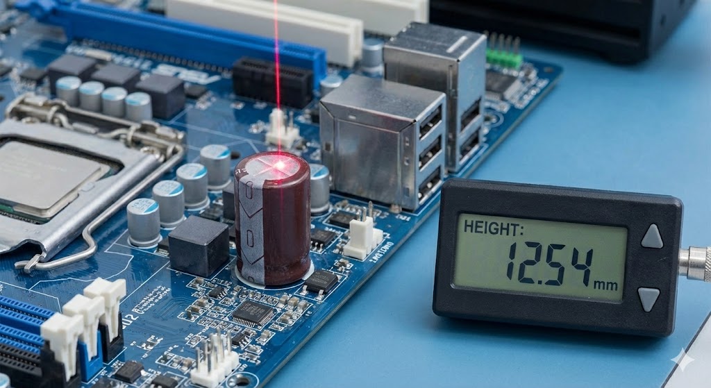
Next, proceed with electrical and interface configuration. Connect the sensor to a stable power supply, adhering to voltage and current ratings to prevent electrical noise or damage. Most industrial line lasers use digital interfaces like Ethernet/IP, PROFINET, or EtherCAT, or analog outputs (0-10V, 4-20mA). Configure the communication parameters in the sensor’s software or PLC to match the network settings. Set the sampling rate and exposure time appropriately: a high rate suits fast-moving objects but may increase noise, while exposure time affects line brightness—too low causes a faint line, too high leads to saturation.
Software calibration is the core of debugging. Launch the manufacturer’s configuration software (e.g., Keyence’s LM Navigator, Cognex’s VisionPro, or SICK’s SOPAS). Begin by capturing a reference profile of a known flat or master workpiece. Use this to define the coordinate system and set the zero point. Adjust parameters like threshold level to distinguish the laser line from background illumination, and filter settings (median or averaging filters) to smooth data. For applications measuring height or depth, map sensor pixels to real-world units (microns or millimeters) using calibration targets. Dynamic compensation may be needed if the target material, color, or reflectivity varies; glossy surfaces can over-saturate the detector, while dark matte surfaces may absorb too much light. Some sensors offer automatic gain control or multi-exposure modes to handle such variations.

Common issues during debugging include a missing or broken laser line, erratic measurements, or communication failures. If the laser line is invisible, check power connections, ensure the safety interlock (if present) is engaged, and verify the emitter isn’t obstructed. A fragmented line often indicates improper focus or dirty optics—clean lenses with approved materials. For noisy or jumping data, investigate environmental factors: ambient light interference (use protective shrouds or filters), electrical grounding problems, or mechanical vibrations. Inconsistent measurements across different materials may require adjusting the exposure or using software compensation profiles. Communication errors typically stem from incorrect IP settings, cable faults, or protocol mismatches—use network analyzers or ping tests to diagnose.
Advanced troubleshooting involves analyzing raw sensor data. Many software tools provide real-time profile displays and histogram analysis. Look for anomalies like spikes or dropouts in the profile, which could indicate surface defects or alignment issues. Log data over time to identify intermittent problems. For multi-sensor setups, synchronize triggers to avoid conflicts. Regularly validate calibration with certified gauge blocks or artifacts, documenting results for quality audits.
Preventive maintenance ensures sustained performance. Schedule periodic recalibration, especially after environmental changes (temperature swings, humidity). Keep optical surfaces clean and inspect cables for wear. Train operators on basic checks, such as verifying the laser line integrity and monitoring for drift.
In summary, debugging line laser sensors is a blend of precise mechanical setup, careful parameter tuning, and methodical fault isolation. By following these steps, engineers can optimize sensor performance, reduce downtime, and enhance the accuracy of automated systems. Always consult the sensor’s manual for model-specific details, as technologies like confocal or spectral interferometry may have unique requirements.