Installing a laser distance sensor correctly is critical for ensuring accurate, reliable, and long-term performance in industrial automation, robotics, and measurement systems. As an experienced electrical engineer, I will guide you through a professional, step-by-step installation process, highlighting key considerations to avoid common pitfalls.
The first and most crucial phase is Pre-Installation Planning and Safety. Before handling the sensor, conduct a thorough risk assessment of the installation environment. Laser sensors, typically falling under Class 1 or Class 2, are generally eye-safe but require respect. Always consult the manufacturer's datasheet for specific safety classifications and warnings. Ensure all power to the system is locked out and tagged out (LOTO). Next, verify the sensor's specifications against your application requirements: measuring range, accuracy, repeatability, response time, and the required output signal (e.g., 4-20mA analog, RS-485, Ethernet/IP, PROFINET). Consider environmental factors such as ambient light (sunlight or strong artificial light), dust, fog, temperature extremes, and potential mechanical vibrations or shock. These factors will influence sensor selection and mounting strategy.
Step 1: Mechanical Mounting.
Choose a stable, rigid mounting surface to minimize vibration-induced measurement errors. Use the recommended bracket or a custom machined fixture that provides precise alignment. The sensor must be mounted perpendicular to the target surface for optimal performance. Any angular deviation introduces a cosine error, reducing accuracy. For dynamic measurements on moving targets, ensure the mounting point is free from the vibration source. Use locking washers or thread-locking compound on all fasteners to prevent loosening over time. Allow adequate clearance around the sensor for ventilation, cable bending, and potential maintenance access.
Step 2: Electrical Connections.
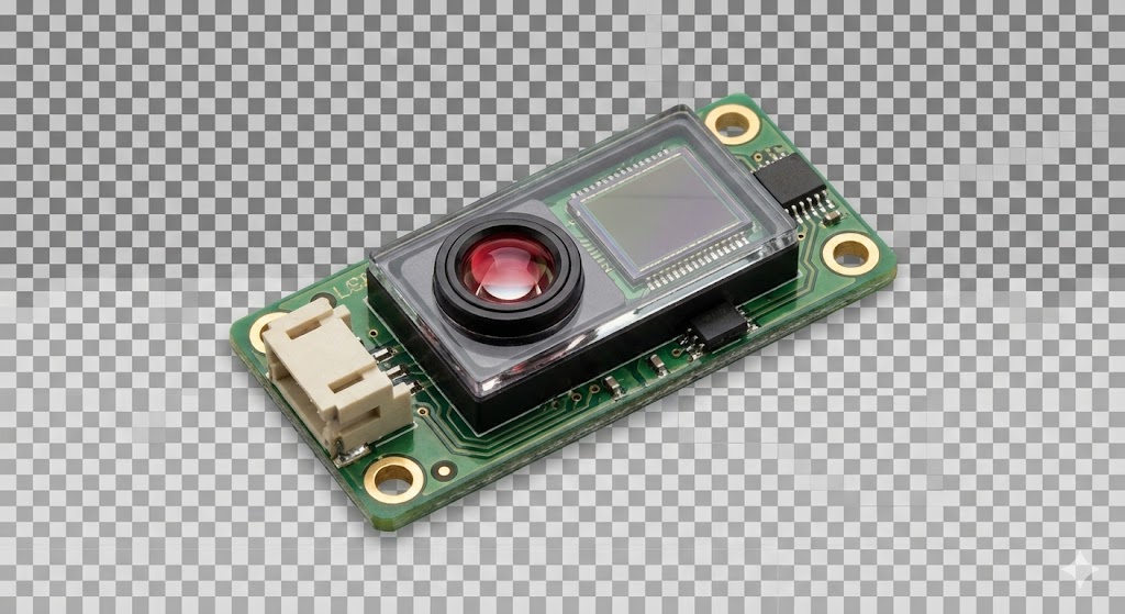
Refer to the sensor's wiring diagram meticulously. Most industrial laser sensors have a multi-pin M12 or M8 circular connector, or terminal blocks. Common connections include power supply (typically 10-30V DC), ground (0V), and output signals. Double-check the polarity; reversing power and ground can instantly damage the device. For analog output sensors, connect the current loop to the appropriate PLC or controller input card, ensuring the loop is properly terminated. For digital communication (e.g., IO-Link, Modbus), follow the protocol-specific wiring guidelines, paying attention to shield connections for noise immunity. Always use shielded cables and ground the shield at the controller end only to prevent ground loops. Route power cables away from high-voltage AC lines and motor drives to avoid electromagnetic interference (EMI).
Step 3: Alignment and Configuration.
Power on the sensor. Many modern sensors have a visible red laser dot or line for alignment assistance. Precisely aim the laser at the desired measurement point on the target. For difficult surfaces (dark, shiny, or transparent materials), use the manufacturer's recommended methods, such as applying a retro-reflective tape or adjusting the sensor's sensitivity settings via software. Access the sensor's parameterization interface, usually via a built-in teach-button, DIP switches, or dedicated configuration software. Set critical parameters like the measuring window (start and end points), output scaling, response filter settings, and communication addresses. For analog sensors, perform a two-point calibration: teach the sensor the output value at a known minimum distance and a known maximum distance.

Step 4: Testing and Validation.
Do not assume the system works after a single successful measurement. Perform a full validation cycle. Test the sensor across the entire expected range of target distances, materials, and environmental conditions (if possible). Check for consistency and repeatability. Introduce potential real-world interferences, such as passing objects in the background or temporary ambient light changes, to ensure the sensor ignores them. Monitor the output signal on an oscilloscope or data acquisition system to verify stability and freedom from noise. Document all settings, calibration points, and test results for future reference and troubleshooting.
Step 5: Integration and Documentation.
Integrate the validated sensor signal into your overall control system logic. Program the PLC or controller to handle the input data, applying any necessary scaling or filtering. Implement software-level fault detection, such as monitoring for signal loss, out-of-range values, or communication timeouts. Finally, create comprehensive as-installed documentation. This should include the sensor model and serial number, wiring diagrams, configuration files, calibration certificates, and precise mounting location details. This documentation is invaluable for future maintenance, system expansion, or fault diagnosis.
Common installation errors include incorrect power supply voltage, poor grounding, ignoring environmental limits, inadequate mechanical stability, and neglecting to configure the sensor for the specific target surface. A methodical approach during installation saves significant time and cost associated with downtime and recalibration. A properly installed laser distance sensor becomes a dependable component, providing precise data for critical processes like positioning, inspection, and control, thereby enhancing overall system efficiency and productivity.