Laser vision sensors have become indispensable tools in modern industrial automation, offering high-precision, non-contact measurement and inspection capabilities. Their ability to capture detailed three-dimensional data in real-time makes them ideal for applications ranging from robotic guidance and quality control to reverse engineering and dimensional analysis. This article delves into the fundamental principles and methodologies for modeling laser vision sensors, providing a comprehensive guide for engineers and researchers in the field.
At its core, a laser vision sensor system typically comprises a laser line projector, one or more cameras (often CCD or CMOS), and sophisticated processing software. The fundamental operating principle is based on active triangulation. The laser projector emits a structured light pattern—commonly a line or a grid—onto the target object's surface. The camera, positioned at a known angle relative to the laser source, captures the deformation of this projected pattern. The deformation of the laser line, caused by the object's surface topography, is then analyzed. By applying geometric triangulation principles, the system calculates the three-dimensional coordinates (X, Y, Z) of each point along the laser line relative to the sensor's coordinate frame.
Accurate modeling of this system is paramount for achieving high measurement fidelity. The modeling process involves establishing precise mathematical relationships between the camera's image coordinates (u, v), the laser plane's equation in 3D space, and the resulting world coordinates (X, Y, Z). This is typically achieved through a calibration procedure.
The first critical component is the camera model. The pinhole camera model, augmented with lens distortion parameters, serves as the standard. This model describes the transformation from a 3D world point to a 2D image pixel. Intrinsic parameters, such as focal length, principal point coordinates, and radial/tangential distortion coefficients, define the camera's internal geometry. Extrinsic parameters, comprising a rotation matrix and a translation vector, define the camera's position and orientation in the world coordinate system. Calibration targets, like checkerboards, are used to determine these parameters accurately.
The second component is the laser plane model. The laser projector emits light that forms a precise plane in space. This plane can be defined by its equation in the world coordinate system, often expressed as Ax + By + Cz + D = 0. Determining the coefficients (A, B, C, D) is a crucial step in sensor calibration. A common method involves placing a planar calibration target at several known positions. The laser line is projected onto this target, and the camera captures the line's image. By knowing the 3D position of the target and the corresponding 2D image points of the laser line, the parameters of the laser plane can be solved using linear least-squares or other optimization techniques.
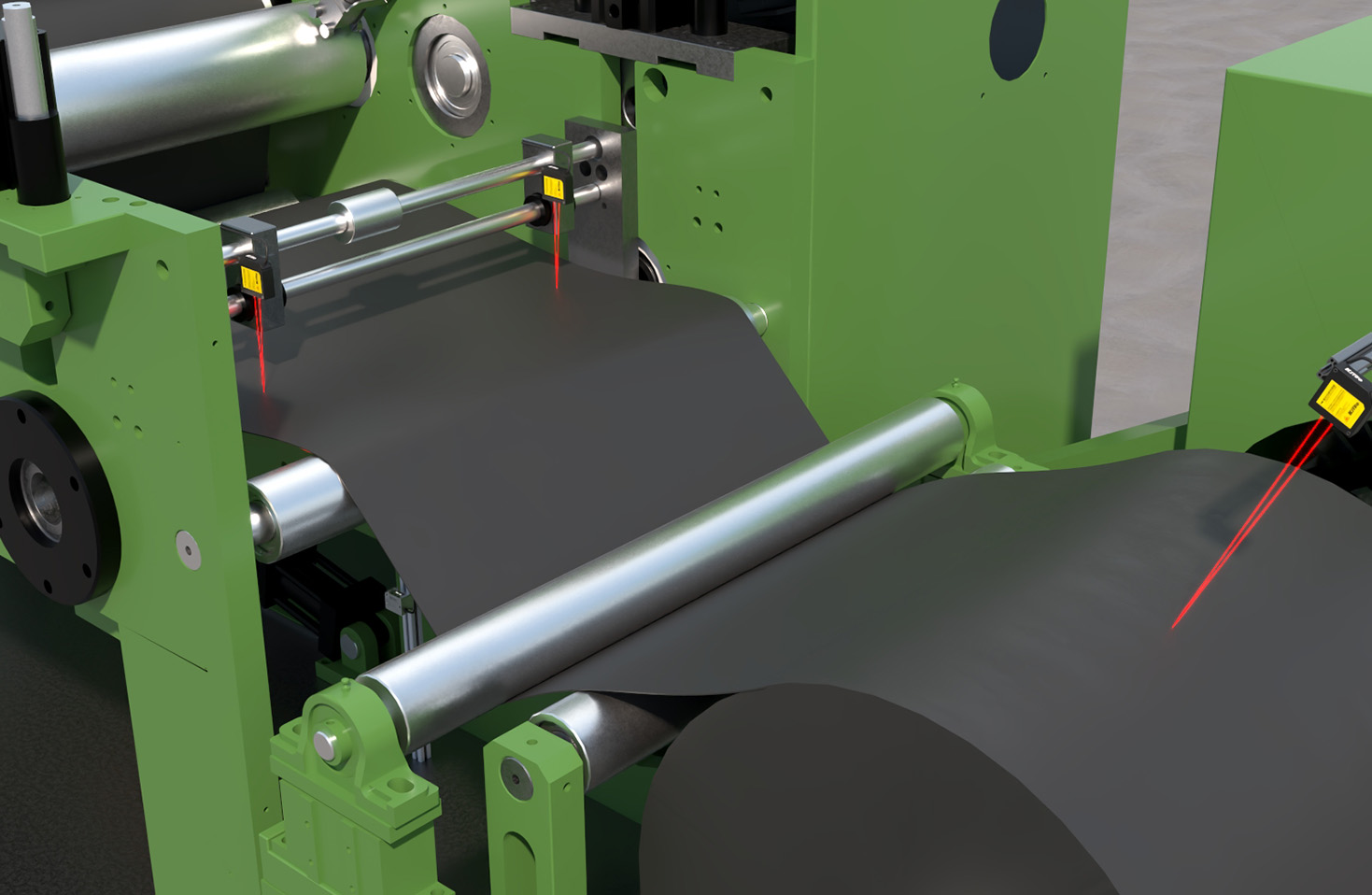
Once both models are established, the 3D reconstruction algorithm can be formulated. For a given pixel (u, v) on the captured laser line in the image, a ray in 3D space is back-projected using the inverse of the camera model. This ray originates from the camera's optical center and passes through the point on the image sensor. The 3D coordinate of the measured point is the intersection of this back-projected ray with the mathematically defined laser plane. Solving this intersection provides the precise (X, Y, Z) coordinates.
Advanced modeling must also account for various error sources and environmental factors. These include sensor noise (both in the camera and laser), ambient light interference, speckle effects from coherent laser light on rough surfaces, and the optical properties of the target material (e.g., reflectivity, translucency). Furthermore, for systems with multiple cameras or laser projectors, the models must be unified into a single coordinate system, requiring rigorous multi-sensor calibration.
In practical industrial deployment, the model's robustness is tested. Factors such as vibration, thermal drift, and mechanical misalignment over time can degrade performance. Therefore, periodic re-calibration or the use of more stable mechanical designs and temperature-compensated components is often necessary. Some modern systems incorporate self-calibration routines or use fiducial markers within the scene to maintain accuracy dynamically.
The choice of modeling complexity also depends on the application. For high-speed, high-accuracy tasks like electronic component inspection or weld seam tracking, sub-micron or micron-level models with compensation for lens distortion and thermal effects are essential. For larger-scale applications like vehicle body-in-white inspection or logistics parcel dimensioning, the model might prioritize speed and robustness over ultimate precision.
Recent trends in modeling involve integrating machine learning techniques. Neural networks can be trained to learn the direct mapping from distorted 2D image patterns to corrected 3D point clouds, potentially bypassing some traditional geometric modeling steps and compensating for complex, non-linear errors in an end-to-end manner. However, the interpretability and data requirements of such approaches remain active research areas compared to well-understood physical models.
In conclusion, effective modeling of laser vision sensors is a multidisciplinary endeavor combining optics, photogrammetry, computer vision, and software engineering. A well-calibrated and accurately modeled sensor is the foundation for reliable automation. As industrial demands for precision, speed, and flexibility continue to grow, ongoing advancements in modeling techniques—from refined physical models to data-driven approaches—will ensure laser vision sensors remain at the forefront of industrial metrology and automation solutions. Engineers must carefully select and implement the appropriate model based on their specific application requirements and operational constraints.