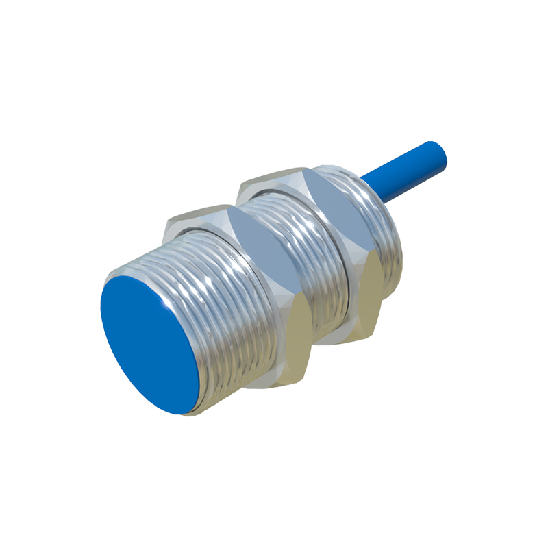
Proximity sensors, often inductive or capacitive types, have become a staple in modern 3D printer auto-bed leveling systems. Unlike mechanical probes, they detect the print bed without physical contact, using electromagnetic fields. While this eliminates wear, achieving perfect sensor leveling is a critical and often misunderstood step for flawless first layers. This guide details the process, emphasizing calibration and troubleshooting.
The core principle is that the sensor must be precisely aligned relative to the nozzle. The goal is not to level the bed to the sensor, but to tweak the sensor's trigger point so that the nozzle's subsequent movement, guided by the sensor, results in a perfectly parallel nozzle-to-bed distance across the entire build plate. A misaligned sensor will cause the printer to create a tilted "virtual bed," leading to inconsistent first-layer squish.
The process begins with mechanical preparation. Ensure your printer's frame is square and the gantry is tight. Manually level the bed as closely as possible using the traditional paper method. This provides a solid starting point. Next, physically mount the sensor securely to the toolhead. The distance between the sensor's detection face and the nozzle tip is its Z-offset from the toolhead. This mechanical offset must be consistent and known; typically, it's fixed by the mount design.
The crucial software configuration involves two main values: the Nozzle-to-Probe Offset and the Probe Z-Offset. The Nozzle-to-Probe Offset (e.g., X=-25, Y=-5) defines the sensor's detection point relative to the nozzle's position in the X and Y axes. This must be measured accurately with calipers and entered into the firmware. An error here will skew all leveling measurements.

After setting the XY offset, you must determine the Probe Z-Offset or Probe Trigger Height. This is the distance between the bed and the nozzle when the sensor triggers. Modern firmware like Marlin or Klipper includes a procedure for this. Heat your bed and nozzle to operating temperatures, as thermal expansion changes distances. Use the firmware's "Z-Offset Calibration" or "Probe Calibrate" function. Manually move the nozzle to a point above the bed, then use a piece of paper or a feeler gauge. Lower the nozzle until you feel slight resistance—this is your Z=0 (nozzle zero). Now, command the sensor to probe the same point. The firmware will calculate the difference between the mechanical Z=0 and the sensor's trigger height, giving you the Probe Z-Offset value. This value can be positive or negative and must be saved to the printer's EEPROM.
With offsets configured, run a full automated bed leveling routine (e.g., G29 in Marlin). This commands the printer to probe a grid of points (e.g., 3x3, 5x5) and create a mesh map of bed height variations. Visually inspect the generated mesh. It should show minor deviations (e.g., +/- 0.1mm). A mesh showing a severe, consistent tilt (e.g., a gradient from +0.3 to -0.3) often indicates that the sensor itself is not perpendicular to the bed or that the Nozzle-to-Probe XY offset is incorrect. A perfectly trammed bed and a correctly configured sensor should yield a relatively flat mesh.
Common issues include inconsistent triggering, often due to a non-metallic print surface (for inductive sensors) or a surface that is too thick/dark (for some capacitive sensors). Ensure your sensor is compatible with your bed material. Inductive sensors require a ferromagnetic metal (like spring steel) and may not work through glass or BuildTak. Electrical noise from heaters or motors can also cause false triggers; proper shielding and separating cables can help.
Finally, remember that sensor leveling complements, but does not replace, a mechanically sound machine. Regularly check the sensor's mounting for looseness and re-run the Z-Offset calibration if you change nozzles or beds. The ultimate test is a live first layer print; adjust the global Z-Offset in fine increments (0.025mm steps) during a skirt or brim print until the filament adhesion and squish are perfect. Patience and meticulous attention to these offsets are the true keys to mastering proximity sensor leveling.