Proximity sensor modules are essential components in modern industrial automation, offering non-contact detection of metallic or non-metallic objects. Proper wiring is critical to ensure reliable operation, safety, and longevity of these devices. This guide outlines standard wiring practices for common proximity sensor modules, including two-wire, three-wire, and four-wire configurations, tailored for engineers and technicians in the electrical and automation fields.
Two-wire proximity sensors are the simplest type, often used in basic AC or DC circuits. They connect in series with the load, similar to a switch. For AC models, typically brown (or black) wire connects to the positive phase, while blue wire links to the load and neutral. In DC versions, brown is usually for positive supply, and blue for negative. These sensors have inherent voltage drop, so ensure the residual voltage at the load meets system requirements. Always verify compatibility with control devices like PLCs or relays to avoid malfunction due to leakage current.
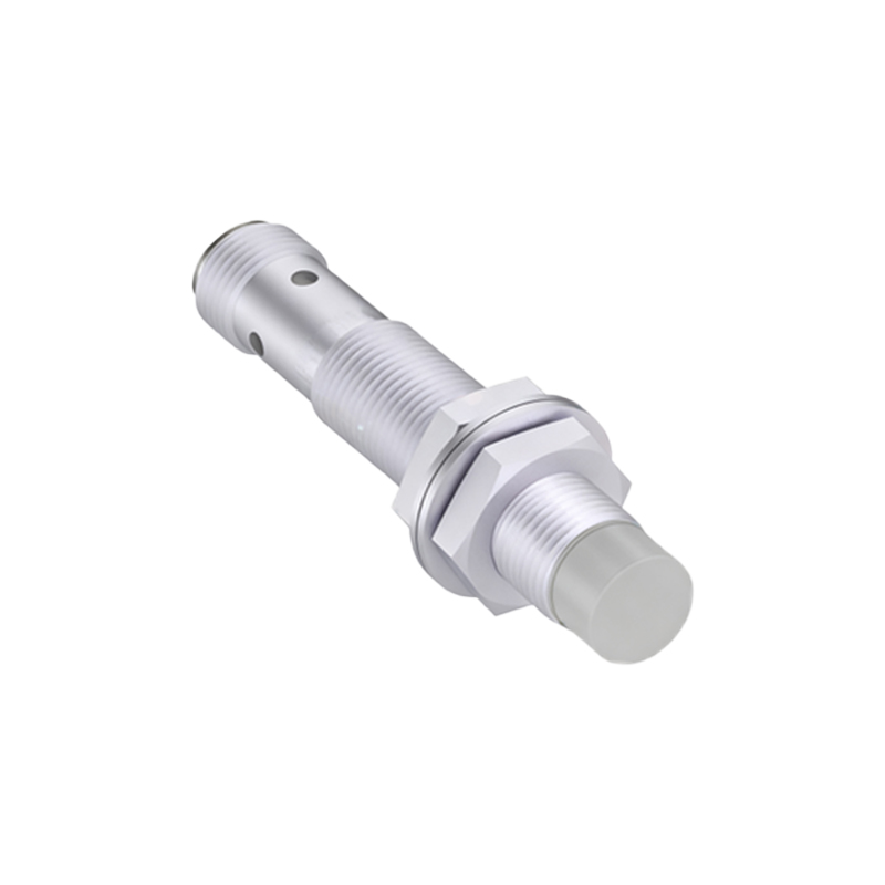
Three-wire sensors are more prevalent in industrial settings due to separate power and output lines, reducing leakage issues. They come in NPN (sinking) and PNP (sourcing) types. For a typical DC three-wire sensor: brown wire connects to positive supply (+V), blue to negative or ground (0V), and black is the output signal. In NPN configurations, the output switches the negative side, meaning the black wire connects to the load, which is then linked to positive. Conversely, PNP sensors switch the positive side, with black wire supplying power to the load when activated. Always match the sensor type (NPN/PNP) with the controller input specifications. Shielding and proper grounding of the blue wire minimize electrical noise interference.
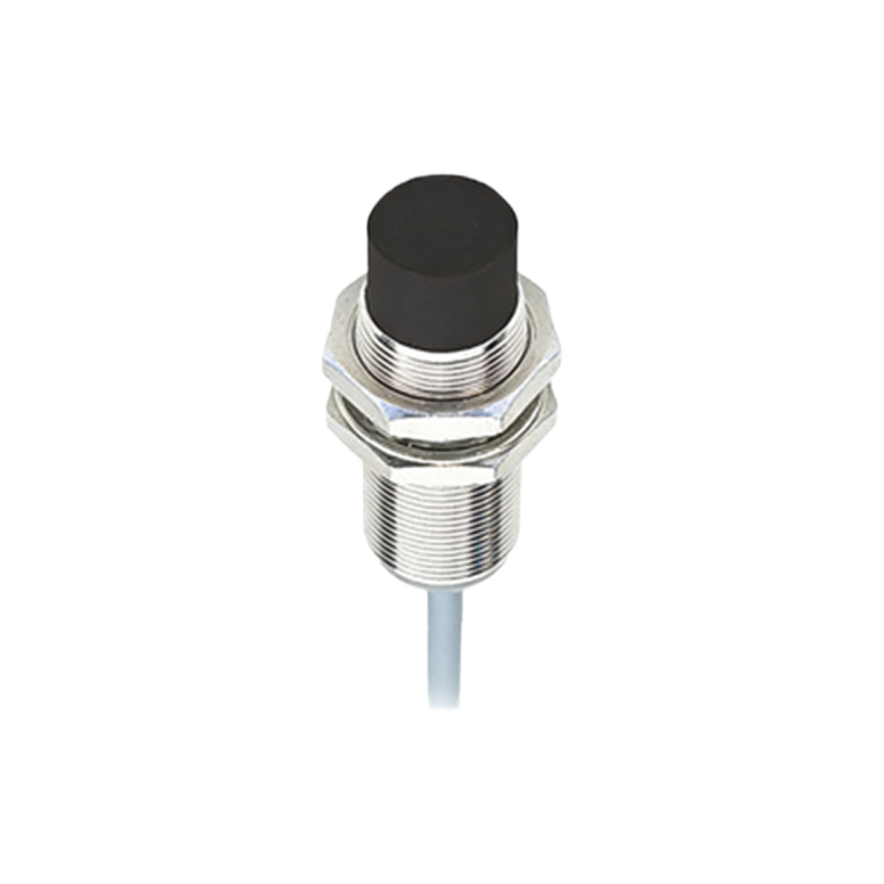
Four-wire sensors include two output channels, often one NPN and one PNP, or complementary outputs for flexibility. Wiring follows similar principles: brown for +V, blue for 0V, with black and white wires as independent outputs. These allow connection to multiple devices or dual safety circuits. Some models feature NO (normally open) and NC (normally closed) outputs—check datasheets to identify wire functions. Use twisted-pair cables for long runs to reduce electromagnetic interference, and avoid routing sensor cables parallel to high-voltage power lines.
Key considerations for all wiring include voltage ratings, current capacity, and environmental factors. Select cables rated for industrial use, such as PVC or PUR sheathed types, with appropriate IP ratings for moisture and dust protection. Implement surge protection devices near sensors in areas prone to voltage spikes. For network-integrated sensors like IO-Link models, follow manufacturer pinouts: typically, pin 1 for +V, pin 3 for 0V, and pin 4 for data, with shielded connectors for signal integrity.
Testing and maintenance are vital. Use multimeters to verify voltage levels and continuity before commissioning. Ensure proper insulation and strain relief at cable entries to prevent breakage. Regular inspections for corrosion or loose connections can preempt failures. Adhering to these wiring standards enhances system reliability, reduces downtime, and aligns with industry norms like IEC 60947-5-2 for proximity switch performance. Always consult module-specific manuals, as color codes may vary by manufacturer—when in doubt, prioritize electrical diagrams over assumed conventions.