In modern industrial automation and smart device applications, integrating sensors with actuators like fans is a fundamental task for creating responsive systems. One common and effective pairing is connecting a laser sensor to control a cooling or exhaust fan. This setup enables the fan to activate automatically based on the detection of specific conditions, such as the presence of an object, excessive heat, or particulate matter. This article provides a detailed, step-by-step guide for engineers and technicians on how to properly interface a laser sensor with a fan, covering essential components, wiring configurations, and control logic.
First, it is crucial to understand the core components involved. A typical laser sensor, such as a diffuse or through-beam type, outputs a digital or analog signal upon detecting a target within its range. Common output types include NPN (sinking) or PNP (sourcing) transistor outputs, relay contacts, or analog voltage/current signals (e.g., 0-10V, 4-20mA). The fan, usually a DC brushless fan for its reliability and controllability, requires a power supply and a method to switch or modulate its speed. For basic on/off control, a relay or a solid-state switch is often used. For variable speed control, a motor driver or a PWM (Pulse Width Modulation) controller is necessary.
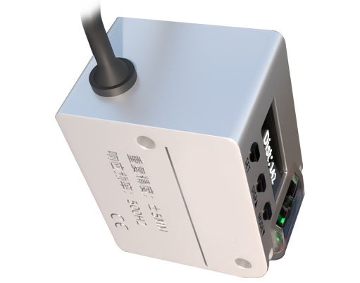
The primary consideration is matching the sensor's output capability with the fan's control input. For a simple on/off application using a digital sensor output, follow these steps. Begin by ensuring all power is disconnected. Identify the sensor's output terminals. For a sensor with a relay output, connect the common (COM) terminal to one side of the fan's power supply line. Connect the normally open (NO) terminal to the other side of the fan's power line. This essentially places the sensor's internal relay in series with the fan. When the sensor detects the target, the relay closes, completing the circuit and powering the fan. For sensors with transistor outputs (NPN/PNP), an external relay or a solid-state switch is typically required because the sensor's output current is usually too low to drive a fan directly. Connect the sensor output to the control input of the relay module. Then, wire the fan through the relay's switched contacts. Always refer to the datasheets for voltage and current ratings to prevent damage.
When using an analog output sensor to proportionally control fan speed, the process involves an intermediate controller. The analog signal (e.g., 0-10V representing distance or intensity) must be read by a device like a PLC (Programmable Logic Controller), an Arduino, or a dedicated fan speed controller. This controller then generates a corresponding PWM signal to adjust the fan's RPM. Connect the sensor's analog output to an analog input on the controller. Program the controller with the desired logic: for instance, map a 0-10V input to a 0-100% PWM duty cycle output. The PWM output pin is then connected to the PWM control wire of a 4-wire DC fan (typically the blue wire). The fan's power (red and black wires) is connected to a suitable DC power source. This allows the fan speed to vary smoothly based on the sensor's reading, ideal for thermal management where speed should increase with detected temperature rise.
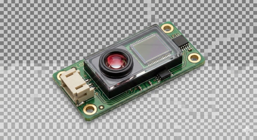
Safety and reliability are paramount. Always use appropriate wire gauges for the current draw of the fan. Implement fuses or circuit breakers on the power lines. For noise suppression in DC circuits, consider adding a flyback diode across the fan terminals to protect against voltage spikes when the power is switched off. Ensure proper grounding of all components. When dealing with mains-voltage AC fans, extreme caution is required; it is highly recommended to use an isolated relay or contactor, and such work should only be performed by qualified personnel.
Testing and calibration are the final steps. Apply power to the sensor and control circuit first, separately from the fan power if possible. Verify the sensor's output signal with a multimeter or oscilloscope when the target condition is met. Then, energize the fan circuit and observe its response. Adjust sensor sensitivity or controller setpoints as needed. For instance, in a cooling application, you might set the fan to turn on only when the laser sensor detects an object (like a hot component on a conveyor) for more than two seconds, preventing false triggers.
This integration of a laser sensor and fan exemplifies a basic yet powerful automation block. It finds applications in server rack cooling, industrial machinery guarding, ventilation systems activated by occupancy, and automated production lines. By mastering this connection, engineers can build more complex, efficient, and intelligent systems tailored to precise environmental or process control demands.