In modern industrial automation and precision measurement, the integration of laser sensors with computer systems is fundamental for real-time data acquisition, process control, and quality assurance. Laser sensors, known for their high accuracy, non-contact measurement, and rapid response, are extensively used in applications ranging from dimensional gauging and object detection to alignment and vibration analysis. Connecting these sensors to a computer unlocks their full potential, enabling sophisticated data logging, analysis, and integration into larger control systems. This guide outlines the standard methodologies and best practices for establishing a reliable connection between a laser sensor and a computer.
The first step involves understanding the output interface of the laser sensor. Most contemporary laser sensors provide digital or analog output signals. Common digital interfaces include RS-232, RS-485, USB, and Ethernet (TCP/IP). Protocols like Modbus RTU over RS-485 or Modbus TCP over Ethernet are industry standards. For analog sensors, the output is typically a voltage (e.g., 0-10V) or current (e.g., 4-20mA) signal proportional to the measured value.
For digital interfaces, the connection process is often straightforward. A sensor with a USB output can usually be connected directly to a computer's USB port. Upon connection, the computer may automatically install a generic driver, but it is crucial to install the specific software or driver provided by the sensor manufacturer for full functionality and configuration. For RS-232 or RS-485 connections, a serial communication port (COM port) is required. Most modern laptops lack native COM ports, necessitating the use of a high-quality USB-to-Serial adapter. After physically connecting the sensor to the computer via the appropriate cable and adapter, the correct COM port must be identified and configured within the sensor's software or a terminal program. Parameters such as baud rate, data bits, parity, and stop bits must match the sensor's settings exactly.
Ethernet-enabled sensors offer the advantage of network connectivity. Connect the sensor to a local network switch or directly to the computer's Ethernet port using a standard CAT5e/CAT6 cable. The sensor will have a default IP address, which may require configuration to match the computer's network subnet. Using the manufacturer's configuration tool or a web browser (if the sensor has an embedded web server), you can set the IP, subnet mask, and gateway. Communication is then established using socket programming or dedicated software that supports the sensor's protocol.

Connecting an analog laser sensor requires an Analog-to-Digital Converter (ADC). This hardware interface, often in the form of a data acquisition (DAQ) card or USB DAQ module, converts the continuous voltage or current signal into a digital value the computer can process. The DAQ device is installed in the computer (PCI/PCIe card) or connected via USB. The sensor's output wires are connected to the specified terminals on the DAQ device. Subsequently, software—such as National Instruments LabVIEW, MATLAB, or the DAQ manufacturer's own application—is used to read the digitized values, apply scaling (converting volts to engineering units like millimeters), and log or display the data.
Regardless of the interface, software is the critical component that bridges the hardware and the user. Manufacturers typically provide proprietary configuration and data visualization software. For more flexible system integration, programmers can use various languages (Python with PySerial or socket libraries, C#, etc.) to develop custom applications for reading data, implementing control logic, and storing results in databases. When developing such applications, robust error handling for communication timeouts and checksum verification is essential for industrial reliability.
Key considerations for a stable connection include electrical noise immunity, cable length limitations, and proper grounding. For long-distance runs or noisy environments, RS-485 or Ethernet is preferable to RS-232. Shielded cables should be used and grounded at one end to prevent electromagnetic interference from corrupting signals. Always consult the sensor's datasheet for specific wiring diagrams, pinouts, and communication command sets.
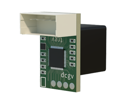
In conclusion, successfully connecting a laser sensor to a computer is a systematic process of matching the physical interface, configuring communication parameters, and implementing software for data handling. This integration forms the backbone of intelligent measurement systems, driving efficiency and precision in modern manufacturing and research environments.