In modern industrial automation and precision measurement systems, laser sensors have become indispensable components due to their high accuracy, non-contact operation, and rapid response capabilities. Understanding the electrical schematics of these sensors is crucial for engineers involved in design, installation, troubleshooting, and maintenance. This article provides a detailed overview of typical laser sensor electrical diagrams, covering key components, signal flow, and practical considerations for integration.
A standard laser sensor electrical schematic primarily consists of three core sections: the power supply circuit, the laser emitter drive circuit, and the photodetector signal processing circuit. The power supply section typically operates on DC voltages, commonly 12V or 24V, with built-in protection against reverse polarity, overvoltage, and transient spikes. Engineers must ensure stable voltage input, as fluctuations can directly impact sensor performance and longevity. Decoupling capacitors and voltage regulators are often integrated to filter noise and maintain consistency.
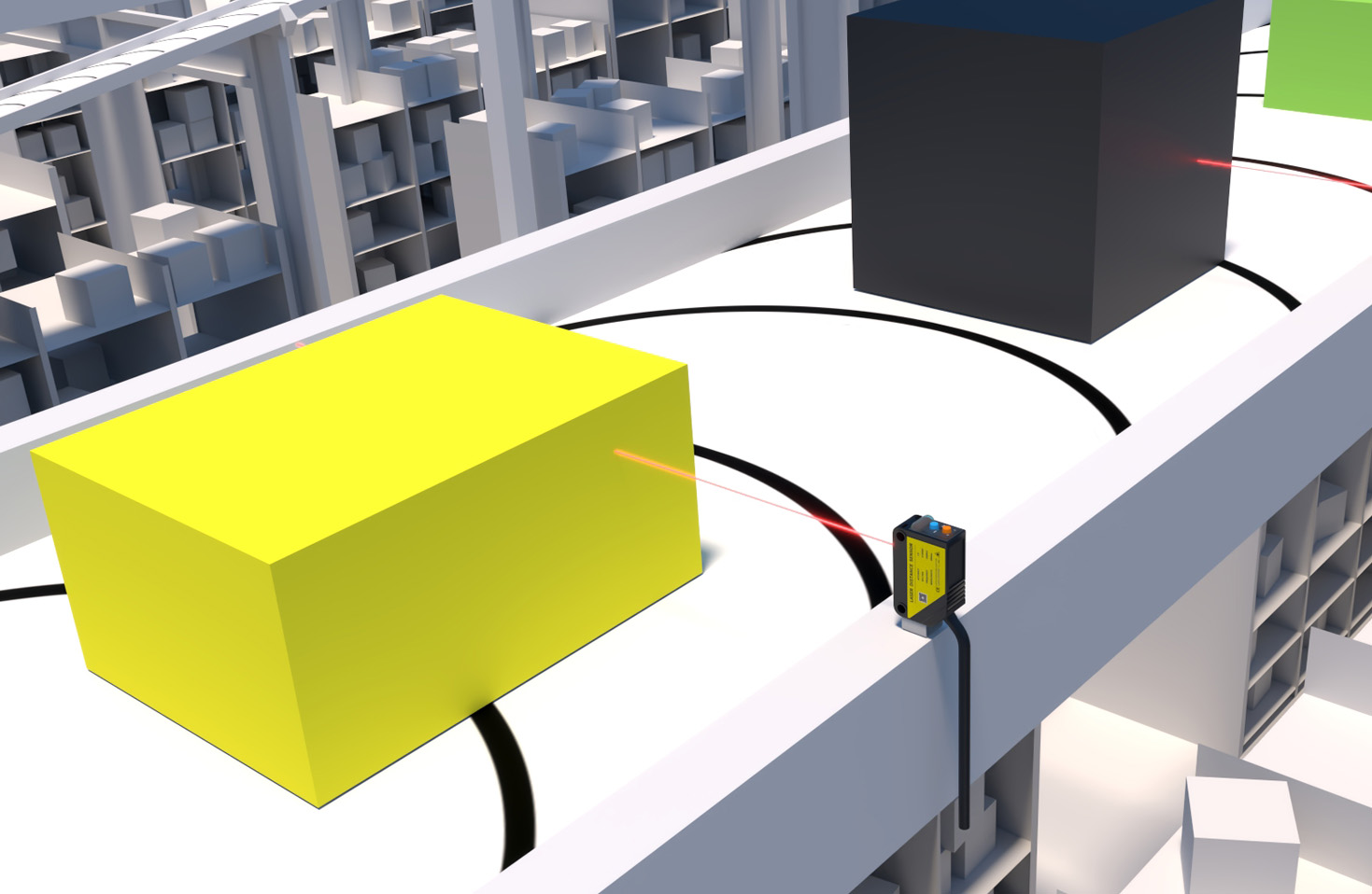
The laser emitter circuit drives the laser diode, which emits a focused beam toward the target. This circuit includes a constant current source to stabilize the laser output, preventing intensity variations due to temperature changes or power supply drift. A modulation circuit may be present for sensors using pulsed or amplitude-modulated light to enhance immunity to ambient light interference. Thermal management components, such as thermistors or Peltier coolers, are sometimes included in the schematic to maintain optimal operating temperatures, especially in high-precision applications.

On the receiving end, the photodetector circuit captures the reflected or interrupted laser beam. This section features a photodiode or phototransistor connected to a transimpedance amplifier, which converts the weak photocurrent into a measurable voltage signal. Subsequent stages often include filters (low-pass or band-pass) to eliminate electrical noise and ambient light artifacts, followed by comparators or analog-to-digital converters (ADCs) for signal conditioning. The output stage provides the final signal, which can be analog (e.g., 0-10V, 4-20mA) or digital (e.g., NPN/PNP open collector, push-pull, or serial communication protocols like IO-Link).
Interfacing laser sensors with control systems requires careful attention to wiring details depicted in schematics. For digital outputs, load connections must match the sensor’s switching logic (sourcing vs. sinking). Shielded cables are recommended for analog signals to minimize electromagnetic interference (EMI). Many schematics also include diagnostic features, such as LED indicators for power status or fault detection, and teach-in buttons for configuration.
Safety considerations are paramount. Laser sensors, particularly Class 2 or higher, incorporate interlock circuits and emission indicators in their electrical designs to comply with international standards like IEC 60825. Engineers should verify that protective earth connections are properly implemented to prevent electrical hazards.
In practice, interpreting a laser sensor schematic involves analyzing timing diagrams for response times, understanding hysteresis settings for threshold detection, and considering environmental factors like dust or vibration that may necessitate additional sealing or damping components. Familiarity with manufacturer-specific symbols and notations is essential, as schematics can vary between brands.
For troubleshooting, a multimeter or oscilloscope can be used to trace signals through the circuit, checking for continuity, voltage levels, and waveform integrity. Common issues include faulty power connections, degraded laser diodes, or contaminated optics, all of which can be diagnosed by referencing the electrical diagram.
As technology advances, laser sensor schematics are evolving to include integrated microcontrollers for smart features like self-calibration, data logging, and network connectivity. Engineers must stay updated with these trends to leverage full sensor capabilities. Ultimately, mastering laser sensor electrical schematics enhances system reliability, reduces downtime, and ensures precise operation in applications ranging from manufacturing and robotics to medical devices and automotive assembly.