In the realm of air quality monitoring, laser dust sensors have become a cornerstone technology for detecting and quantifying particulate matter (PM) concentrations. These compact devices, often found in consumer-grade air purifiers, industrial monitors, and smart home systems, offer a significant advancement over older infrared-based methods in terms of accuracy and sensitivity, particularly for fine particles like PM2.5 and PM1.0. This article provides a detailed technical disassembly and analysis of a typical laser dust sensor module, exploring its internal architecture, operational principles, and key components. Our subject is a common module utilizing the light scattering principle, often branded with model numbers like PMS5003 or similar.
The external housing of the sensor is typically a robust, injection-molded plastic case designed to create a controlled airflow path. Small inlet and outlet vents guide ambient air through the sensing chamber. The first step in disassembly involves carefully removing several small Phillips-head screws securing the top and bottom halves. Upon opening, the internal layout is immediately apparent: a main printed circuit board (PCB) hosts the majority of the electronics, while a separate, meticulously designed optical chamber is the heart of the device.
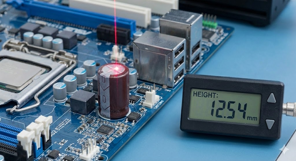
The optical chamber is a critical, often blackened, plastic compartment designed to minimize internal light reflections (stray light) that could cause measurement noise. A focused laser diode, usually operating in the 650-680nm (red) wavelength range, is mounted on one side. This laser shines a precise beam across a dark, empty channel—the sample volume—through which the sampled air is drawn. Directly opposite, or at a specific angle (often 90 degrees for side-scatter designs), a highly sensitive photodetector, such as a photodiode or phototransistor, is positioned. Its role is to detect the minute flashes of light (scattered radiation) when a dust particle passes through the laser beam. The geometry of this chamber, the laser's focus, and the detector's placement are all optimized to maximize signal-to-noise ratio for particles in the target size range.
The airflow system is equally deliberate. A small, low-noise fan or a pump, often a diaphragm type, is integrated into the housing. It creates a negative pressure, actively pulling a consistent volumetric flow of air through the inlet, across the sample volume in the optical chamber, and out the exhaust vent. This active sampling is crucial for obtaining real-time, representative measurements, as opposed to passive diffusion.
On the electronic front, the PCB reveals a sophisticated signal chain. The faint analog current pulses from the photodetector are first fed into a transimpedance amplifier (TIA), which converts them into measurable voltage signals. These signals are then conditioned—amplified and filtered—to isolate the particle pulses from electronic noise. A microcontroller unit (MCU), often an ARM Cortex-M core or an 8-bit AVR, sits at the center. It digitizes the conditioned analog signals via an integrated Analog-to-Digital Converter (ADC). The firmware running on this MCU performs the complex algorithms that analyze the pulse heights (correlated to particle size) and pulse counts (correlated to particle concentration) to calculate mass density concentrations for different PM categories. The results are then output via a serial communication interface, commonly UART with a specific protocol, providing real-time data on PM1.0, PM2.5, and PM10.
Key components identified during the teardown include: the laser diode module with its driver circuit for stable operation; the high-sensitivity photodetector; the low-noise operational amplifiers for signal conditioning; the main MCU; the airflow pump; and various passive components for power regulation and filtering. The power supply section typically accepts a wide input range (e.g., 5V DC) and provides clean, regulated voltages for the sensitive analog and digital sections.
From an engineering perspective, several design challenges are evident. Thermal management for the laser diode is critical, as wavelength and output power drift with temperature, potentially affecting calibration. Dust accumulation on the optical windows over time is a major concern for long-term accuracy, which some designs attempt to mitigate with clever airflow patterns or anti-static coatings. Furthermore, the calibration process is non-trivial; sensors are typically calibrated against reference instruments in controlled environments using standardized test dust.
In conclusion, the disassembly reveals that a modern laser dust sensor is a marvel of miniaturized optoelectronics, precision mechanics, and embedded software. Its performance hinges on the synergistic integration of a stable light source, a dark and precise optical chamber, a consistent airflow system, and a low-noise, intelligent signal processing chain. Understanding this internal architecture is essential for engineers looking to integrate these sensors into products, interpret their data accurately, and appreciate their limitations in varying environmental conditions.