Laser sensors are indispensable tools in modern industrial automation, offering high precision, non-contact measurement, and reliability in demanding environments. However, achieving optimal performance requires meticulous calibration and debugging. This guide outlines a systematic approach to setting up and troubleshooting laser sensors, ensuring accurate data acquisition and seamless integration into control systems.
The first step in debugging a laser sensor is understanding its operating principles. Most industrial laser sensors operate on time-of-flight, triangulation, or phase-shift principles. Time-of-flight sensors measure distance by calculating the time taken for a laser pulse to reflect back, ideal for long-range applications. Triangulation sensors use a laser emitter, a receiver, and geometric angles to determine position, excelling in high-resolution short-range tasks. Phase-shift sensors analyze modulation phases for intermediate ranges. Before installation, review the sensor’s datasheet to confirm its specifications, such as measurement range, resolution, response time, and environmental tolerances (e.g., temperature, humidity, and ambient light).
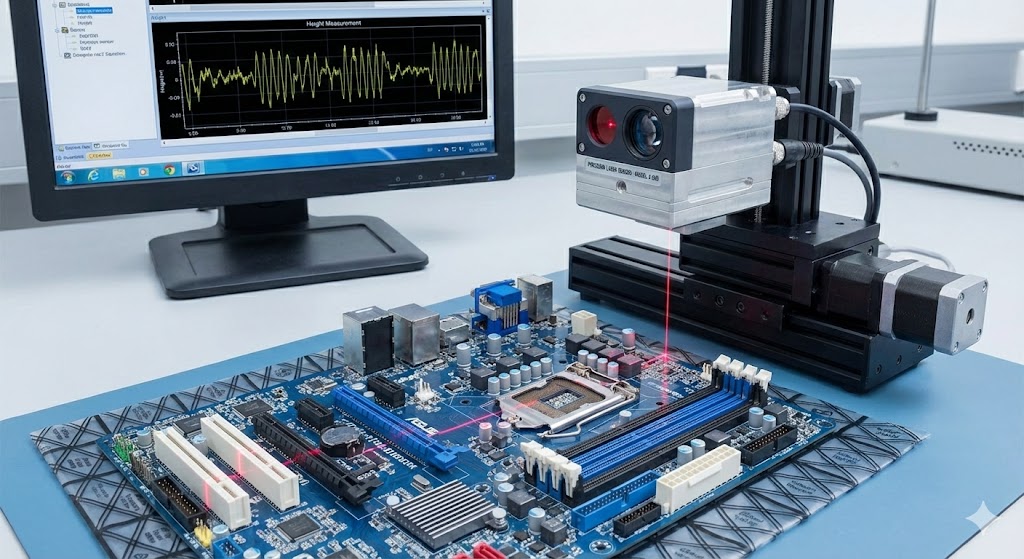
Installation is critical. Mount the sensor securely on a stable platform to minimize vibrations, which can cause measurement drift. Ensure the laser beam is perpendicular to the target surface unless angled measurements are required by design. Avoid placing the sensor near reflective surfaces or intense light sources, as these can interfere with signal integrity. For triangulation sensors, maintain the recommended standoff distance—the gap between the sensor and target—to prevent errors. Use mounting brackets with fine-adjustment capabilities for precise alignment.
Calibration begins with powering the sensor according to manufacturer guidelines, typically using a stable DC power supply to avoid voltage fluctuations. Connect the sensor to a monitoring device, such as a PLC (Programmable Logic Controller) or a dedicated software interface, to observe real-time output. Most sensors provide analog outputs (e.g., 4-20 mA or 0-10 V) or digital interfaces (e.g., IO-Link, Ethernet/IP). Set the output range to match the measured parameter, like distance or thickness. For example, if measuring a 100 mm range, configure 4 mA to represent 0 mm and 20 mA for 100 mm.
Perform a zero-point calibration by placing a reference object at a known distance. Use a calibrated gauge block or a flat surface with certified dimensions. Adjust the sensor’s zero offset until the output matches the reference value. For linearity calibration, test multiple points across the measurement range. Record outputs at minimum, midpoint, and maximum distances, and use sensor software to correct any deviations. Some advanced sensors feature auto-calibration functions that streamline this process.
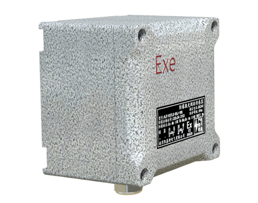
Debugging common issues requires a methodical approach. If the sensor provides erratic readings, check for environmental factors. Dust, smoke, or oil mist can scatter the laser beam, leading to signal loss. Install protective housings or air purges in dirty environments. Ambient light interference, especially from infrared sources, may be mitigated by using sensors with modulated lasers or optical filters. Verify the target’s properties: dark or absorbent materials reduce reflectivity, while shiny surfaces can cause specular reflections. Adjust the sensor’s sensitivity settings or apply retro-reflective tapes to the target if necessary.
Electrical noise is another frequent culprit. Ensure proper grounding and shield cables from high-voltage lines or motor drives. Use twisted-pair cables for analog signals to reduce electromagnetic interference. If the sensor fails to power on, inspect connections for loose wires or incorrect polarity. For digital communication errors, confirm protocol settings (e.g., baud rate, address) and cable integrity.
Software tools provided by manufacturers, such as configuration wizards or diagnostic suites, are invaluable for debugging. They allow users to monitor signal strength, adjust filtering parameters, and log data for analysis. For instance, increasing response time filters can smooth out noise but may delay readings—balance this based on application speed requirements. Regularly update firmware to access bug fixes and enhanced features.
In integration scenarios, validate the sensor’s interaction with broader systems. Test edge cases, like rapid target movements or extreme temperatures, to ensure stability. Document calibration records and maintenance schedules, as sensors may drift over time due to component aging. Recalibrate periodically, especially after mechanical shocks or environmental changes.
Ultimately, successful laser sensor debugging hinges on a blend of technical knowledge and practical vigilance. By following these steps—from installation and calibration to troubleshooting—engineers can maximize sensor lifespan and accuracy, driving efficiency in applications from robotics to quality inspection.