In the realm of industrial automation, proximity switches are indispensable components, serving as non-contact sensors that detect the presence or absence of objects. While their functional specifications are paramount, the customization of proximity switch images—encompassing technical drawings, dimensional diagrams, and application-specific illustrations—plays a crucial role in integration, maintenance, and procurement. This article delves into the technical considerations and best practices for creating and utilizing customized images for proximity switches, tailored to meet the precise demands of diverse industrial environments.
The primary purpose of a customized proximity switch image is to convey exact physical and electrical interfacing information. A standard product catalog image often lacks the specific details required for seamless integration into a unique machine design or control panel. Therefore, a customized technical drawing should include precise dimensional tolerances, mounting hole patterns, sensing range indicators, and connector pinout diagrams. For instance, when integrating a cylindrical inductive proximity switch into a robotic assembly cell, a custom cross-sectional view can clearly illustrate the required clearance zones, thread specifications, and the optimal positioning relative to the target metal component. This level of detail prevents installation errors and ensures the sensor operates within its specified parameters, maximizing reliability and longevity.
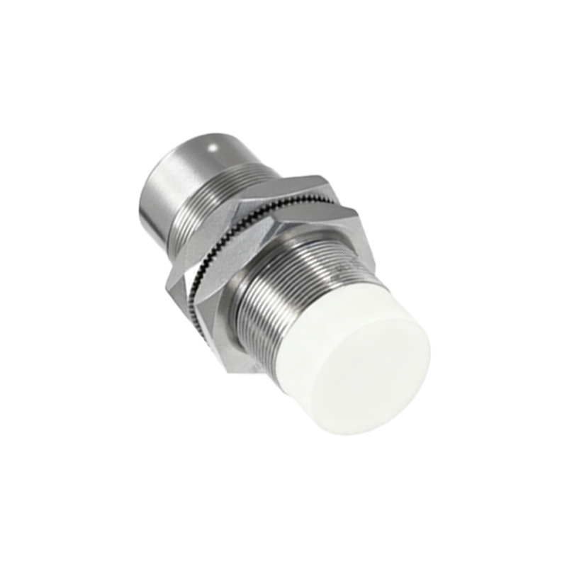
Material and environmental specifications must be visually emphasized in customized imagery. Proximity switches are deployed in harsh conditions—exposed to oils, coolants, extreme temperatures, or washdown procedures. Custom images should annotate critical features such as the housing material (e.g., stainless steel AISI 304/316, nickel-plated brass), IP (Ingress Protection) rating (e.g., IP67, IP69K), and temperature range. A detailed image might use callouts to highlight the hermetic seal location or the material grade of the sensing face. For food and pharmaceutical applications, where sanitary standards are stringent, imagery should underscore smooth surfaces, crevice-free designs, and certifications like FDA compliance or EHEDG approval. Providing these details visually accelerates the material selection process for engineers and procurement specialists.
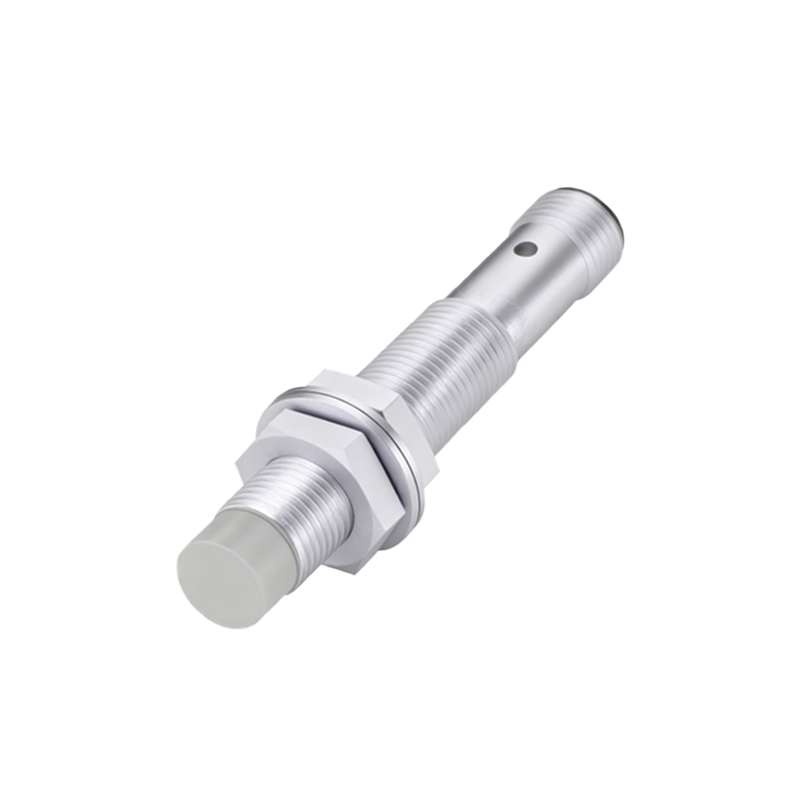
Electrical characteristics are another vital dimension for customization. A schematic diagram integrated into the switch's image set can depict wiring configurations (e.g., NPN/PNP, normally open/normally closed), voltage requirements (10-30V DC, 20-250V AC), and output current ratings. For complex network-integrated sensors, such as those with IO-Link capability, a custom block diagram illustrating the communication interface, data protocol, and parameter assignment becomes invaluable. This visual aid assists control engineers in planning the electrical cabinet layout and programming the PLC logic, reducing commissioning time. Additionally, LED indicator positions and their status meanings (power, output active, diagnostic) should be clearly shown, as they are critical for on-site troubleshooting.
Application-specific scenario illustrations bridge the gap between abstract specifications and real-world utility. Instead of a generic switch graphic, a customized set might include an isometric view of the sensor installed on a conveyor belt, detecting metallic packages, or integrated into a hydraulic cylinder to monitor piston position. These contextual images help clients visualize the solution within their own operations. They can demonstrate the recommended mounting distance, the detection pattern (shielding or non-shielding effect), and potential interference from adjacent metal structures. For challenging applications like detecting small or fast-moving targets, an annotated high-speed photograph or a simulation graphic showing the effective sensing field can be instrumental in validating the switch's suitability.
The process of obtaining customized images typically involves collaboration between the client's engineering team and the sensor manufacturer or a specialized technical illustrator. Clients should provide detailed application parameters: target material (steel, aluminum, plastic, liquid), required sensing distance, operating frequency, environmental challenges, and electrical interface needs. In return, manufacturers can generate 2D CAD drawings (DXF, DWG), 3D models (STEP, IGES), and high-resolution renderings. These digital assets are essential for design-in processes using CAD software, ensuring fit and function before physical prototyping. They also serve as precise references for quality inspection upon receipt of the shipment.
In conclusion, customizing proximity switch images is not merely an aesthetic exercise but a fundamental engineering practice that enhances clarity, ensures compatibility, and mitigates project risk. From detailed dimensional drawings to application-specific diagrams, these tailored visual tools facilitate every stage—from initial design and integration to installation and maintenance. By investing in precise, comprehensive imagery, industrial stakeholders can optimize system performance, reduce downtime, and achieve a higher return on investment in their automation infrastructure. As sensor technology evolves with smarter features, the role of customized technical visualization will only grow in importance for successful implementation.