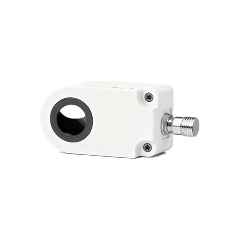
Proximity sensors are pivotal components in modern industrial automation, offering non-contact detection of objects within a specific range. Their structural schematic reveals a sophisticated design tailored for reliability and precision. Typically, a proximity sensor comprises several key parts: the sensing element, oscillator, demodulator, output circuit, and housing. The sensing element, often a coil in inductive sensors or a capacitive plate in capacitive types, interacts with the target object. In inductive proximity sensors, the oscillator generates a high-frequency electromagnetic field around the sensing coil. When a metallic object enters this field, eddy currents are induced, causing a change in the oscillation amplitude. This alteration is detected by the demodulator, which converts it into a DC signal. The output circuit then processes this signal to trigger a switch, such as a transistor or relay, providing a digital or analog output.
The structural schematic illustrates how these components are integrated. For instance, in a standard inductive proximity sensor, the coil is wound around a ferrite core, enclosed in a rugged housing made of materials like nickel-plated brass or stainless steel for durability in harsh environments. The oscillator and demodulator are typically implemented using integrated circuits mounted on a printed circuit board (PCB) within the sensor. The output circuit may include features like short-circuit protection and reverse polarity protection to enhance robustness. Capacitive proximity sensors follow a similar schematic but use a capacitive plate to detect changes in dielectric constant, making them suitable for non-metallic objects.
Understanding the schematic aids in selecting the right sensor for applications. Inductive sensors excel in detecting metals with high repeatability and fast response times, often used in machinery for position sensing or part counting. Capacitive sensors, with their ability to sense liquids, plastics, and other materials, are ideal for level detection or packaging systems. The schematic also highlights design considerations, such as shielding to reduce electromagnetic interference or temperature compensation circuits for stable operation across varying conditions.
In practice, the proximity sensor's schematic translates into reliable performance. For example, in automotive assembly lines, inductive sensors detect metal components without physical contact, minimizing wear and tear. The output signal can interface with programmable logic controllers (PLCs) to automate processes. Maintenance benefits from the schematic too; technicians can troubleshoot issues by referencing component layouts, such as checking the oscillator for proper frequency or inspecting the housing for damage.
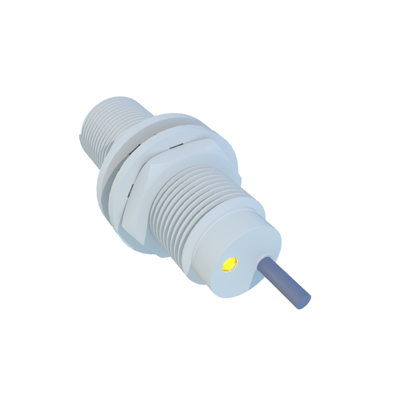
Overall, the structural schematic of a proximity sensor demystifies its operation, showcasing how simple principles like electromagnetic induction or capacitance are harnessed for industrial efficiency. By examining the schematic, engineers can optimize sensor placement, ensure compatibility with control systems, and innovate in automation solutions. As technology advances, schematics may evolve with smart features like IO-Link communication for data exchange, but the core principles remain rooted in this foundational design.