In the realm of industrial automation and control systems, proximity sensors stand as fundamental components for non-contact object detection. Among the various technical specifications that define their performance, the Attenuation Factor 1 (a1) is a critical, yet often misunderstood, parameter. This article delves into the engineering principles behind a1, its practical implications for sensor selection and installation, and its significance in ensuring reliable operation within complex metallic environments.
At its core, the attenuation factor, specifically a1, quantifies the reduction in a proximity sensor's effective sensing distance when the target object is made of a specific material—most commonly, mild steel. The "1" in a1 denotes the standard reference material. By definition, a sensor's rated operating distance (Sn) is calibrated and standardized for a target of mild steel with a1 = 1. This standardized target is typically a 1mm thick square of St37 steel (or equivalent, like Fe 360) with a side length equal to the sensor's diameter or the diameter of the sensing face, whichever is smaller. This establishes a universal baseline for performance comparison.
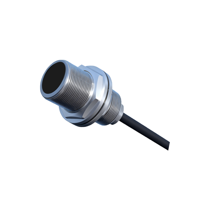
The practical importance of a1 becomes starkly apparent when the target material differs from mild steel. Different materials have varying electromagnetic properties, primarily their permeability and conductivity, which directly influence the eddy currents generated in inductive sensors or the capacitive coupling in capacitive sensors. For instance, non-ferrous metals like aluminum, brass, or copper have lower permeability than steel. Consequently, the sensor's electromagnetic field penetrates these materials differently, resulting in a weaker interaction. This translates to a reduced effective sensing range.
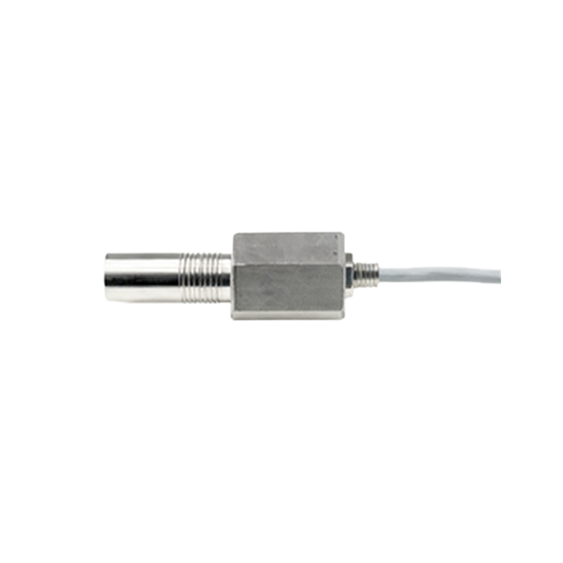
To calculate the effective sensing distance (Seff) for a non-standard target material, a simple formula is applied: Seff = Sn × (a1 of the target material). If a sensor has a rated sensing distance (Sn) of 10mm for mild steel (a1=1), and it is tasked with detecting an aluminum target (which may have an a1 value of approximately 0.3 to 0.4, as specified by the sensor manufacturer), the effective sensing distance drops to just 3-4mm. Failure to account for this attenuation is a common cause of installation failure and system malfunction. Engineers must consult the sensor's datasheet, which should provide a1 values for common materials like stainless steel (often a1 ≈ 0.7-0.9), aluminum (a1 ≈ 0.3-0.45), and copper (a1 ≈ 0.2-0.35).
Beyond the target itself, the concept of attenuation extends to the installation environment. A critical challenge in industrial settings is the presence of surrounding metals—mounting brackets, machine frames, or other sensors. These can cause shielding or flanking effects, effectively attenuating the sensor's field from the sides or rear. Modern sensors are designed with built-in "shielding" or "non-flush mountable" designs that concentrate the electromagnetic field axially forward, minimizing lateral interference and allowing installation flush in metal. Conversely, "unshielded" or "flush mountable" sensors have a larger lateral field and must be installed with a specific clearance from surrounding metal, as defined by the manufacturer, to prevent false triggering or sensing distance reduction. Understanding these designations is paramount for correct mechanical integration.
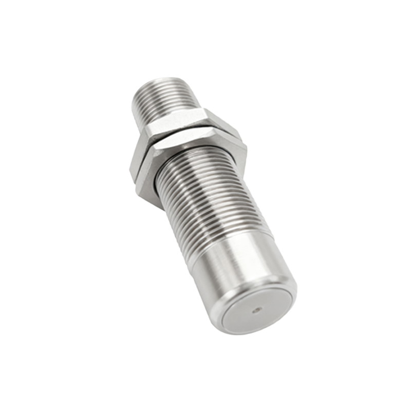
Furthermore, the a1 factor is intrinsically linked to temperature stability and switching frequency. The material properties of both the sensor's coil and the target can drift with temperature, potentially affecting the attenuation characteristic marginally. While high-quality sensors compensate for this internally, it remains a consideration for extreme environments. Additionally, when sensing smaller targets or those with low a1 values, the required oscillation amplitude change for detection might take longer, potentially reducing the maximum achievable switching frequency.
In application engineering, a rigorous workflow is recommended. First, precisely identify the target material and obtain its correct a1 coefficient. Second, calculate the required effective sensing distance based on the mechanical application. Third, select a sensor whose nominal sensing distance (Sn), when multiplied by the target's a1, meets or exceeds this required Seff with a safety margin (often 20-30%). Fourth, adhere strictly to installation guidelines regarding shielding type and mounting clearances. Finally, perform real-world verification tests under actual operating conditions, including temperature cycles and potential contaminant buildup.
In conclusion, the Attenuation Factor 1 is not merely a datasheet entry but a fundamental scaling factor for the operational reality of proximity sensors. It bridges the gap between idealized laboratory specifications and the messy, material-diverse world of industrial automation. A disciplined approach to incorporating a1 into the design and installation phase prevents costly downtime, ensures repeatability, and guarantees the robust performance expected from modern sensing systems. Mastery of this parameter is a hallmark of proficient electrical and automation