Proximity sensors are indispensable components in modern industrial automation, providing non-contact detection of metallic or non-metallic objects. Correct wiring is fundamental to ensuring reliable operation, safety, and longevity of both the sensor and the connected control system. This guide details four common wiring methods for proximity sensors, tailored to different power supplies and output configurations.
Firstly, understanding the basic types is crucial. Proximity sensors are broadly categorized by their output: NPN (sinking) and PNP (sourcing), as well as by their power requirements: DC (typically 10-30V DC) or AC (typically 90-250V AC). Always consult the manufacturer's datasheet for specific voltage, current, and wiring details before installation.
Method 1: Wiring a 2-Wire DC Proximity Sensor
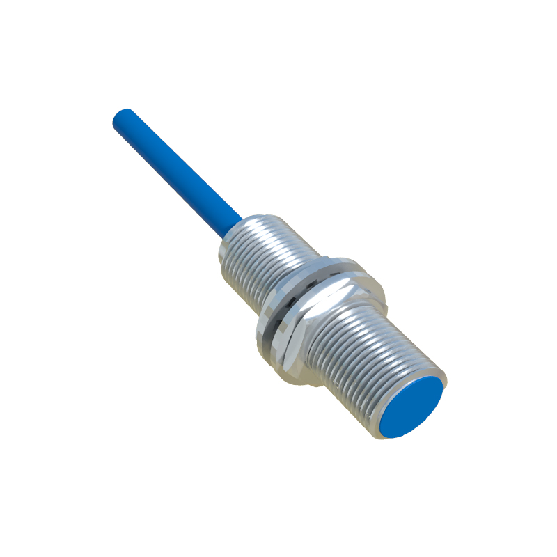
The two-wire DC sensor is the simplest to connect. It has only two terminals: one for power (positive) and one for load (negative). In this configuration, the sensor and the load (e.g., a PLC input or relay coil) are connected in series. Connect the positive lead of the DC power supply to the sensor's brown wire (or designated positive terminal). Then, connect the sensor's blue wire (or load terminal) to one side of the load. Finally, connect the other side of the load back to the negative terminal of the power supply. A key consideration is the residual current or leakage current when the sensor is off, which must be lower than the holding current of the load to prevent unintended activation.
Method 2: Wiring a 3-Wire DC Proximity Sensor (PNP Sourcing Output)
The three-wire DC sensor is the most prevalent in industrial settings due to its clear signal separation. It has three distinct wires: brown (positive), blue (negative/0V), and black (output signal). For a PNP (sourcing) type sensor, the output actively switches the positive voltage. To wire it, connect the brown wire to the positive terminal of your DC power supply (e.g., +24V). Connect the blue wire to the negative terminal (0V or common). The black output wire is then connected to the input point of your controller (like a PLC digital input). The PLC input's common terminal must be connected to the 0V of the same power supply. When a target is detected, the PNP sensor connects the black wire to the internal positive supply, sourcing current to the PLC input.
Method 3: Wiring a 3-Wire DC Proximity Sensor (NPN Sinking Output)
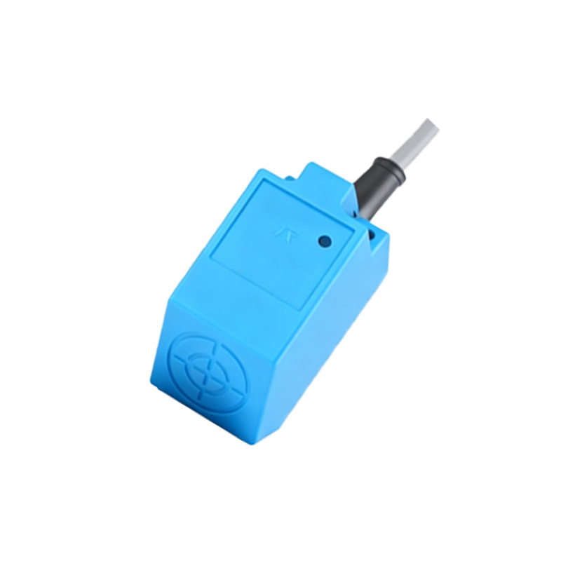
The wiring for an NPN sensor is similar but with a crucial difference in the output behavior. The wire colors are identical: brown (positive), blue (negative), and black (output). Connect the brown and blue wires to the DC power supply as described in Method 2. For the NPN (sinking) type, the black output wire is connected to the PLC input. However, the PLC input's common terminal must now be connected to the positive supply voltage. When activated, the NPN sensor internally connects the black wire to 0V, sinking current from the PLC input to ground. This is a critical distinction; mixing up PNP and NPN wiring will result in a non-functional circuit.
Method 4: Wiring a 2-Wire AC Proximity Sensor
AC-powered proximity sensors are often used in high-voltage environments. They typically have two wires without a polarity distinction. One wire is connected directly to the live (hot) AC line (e.g., 120V AC), and the other wire is connected in series with the load (like an AC coil of a contactor or an AC input module). The other terminal of the load is then connected to the neutral line. It is paramount to observe all local electrical codes and lock-out/tag-out procedures when working with AC power. Ensure the sensor's voltage rating matches the supply voltage, and note that AC sensors may have a slight delay in switching off due to the nature of the alternating current.
Best Practices for All Wiring Methods:
1. Power Disconnect: Always isolate and verify that power is off before beginning any wiring work.
2. Correct Type: Double-check whether you have an NPN, PNP, AC, or DC sensor. The markings on the sensor body (e.g., "PNP NO" for normally open) are your primary reference.
3. Wire Gauge: Use wires of appropriate gauge for the expected current load to prevent overheating.
4. Shielding: In electrically noisy environments, use shielded cables for the signal wire and ground the shield at one end only to the control panel