Proximity sensors are indispensable components in modern industrial automation, providing non-contact detection of objects for applications ranging from assembly line positioning to safety guarding. Their reliability hinges on one critical process: calibration. Proper calibration ensures that a proximity sensor operates at its specified sensing distance with optimal repeatability and immunity to environmental interference. This guide details the essential principles, methodologies, and best practices for calibrating inductive, capacitive, and photoelectric proximity sensors.
The core purpose of calibration is to align the sensor's actual switching point with its nominal or required sensing distance (Sn). Factors such as manufacturing tolerances, target material composition (for inductive sensors), temperature fluctuations, and electrical noise can cause deviations. Calibration corrects these deviations, establishing a precise and reliable operational threshold.
Pre-Calibration Preparation
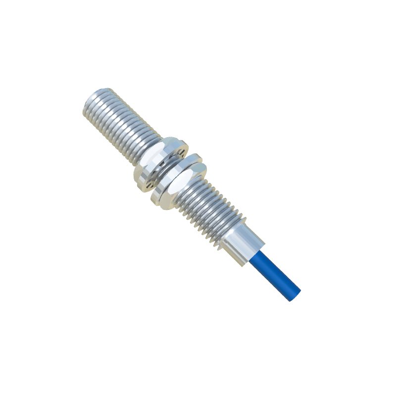
Before initiating calibration, a thorough inspection is mandatory. Ensure the sensor is correctly mounted, free from physical damage, and its sensing face is clean. Verify the electrical connections according to the datasheet, confirming the correct voltage supply and load. The target object used for calibration must be the standard target specified by the manufacturer—typically a square of mild steel (Fe360) for inductive sensors. Environmental conditions should be stable, minimizing the influence of temperature drift, humidity, or strong electromagnetic fields.
Calibration Procedures by Sensor Type
1. Inductive Proximity Sensors: These detect metallic objects. The calibration process involves positioning the standard target axially towards the sensing face. Using a precision positioning fixture or gauge blocks, slowly move the target towards the sensor. The point at which the sensor's output switches state (e.g., from OFF to ON) is the actual sensing point. Compare this to the nominal Sn. Many modern inductive sensors feature a built-in potentiometer or teach-in function. Adjust the potentiometer or activate the teach-in mode with the target at the desired sensing distance to set the switch point. For sensors without adjustment, calibration involves verifying performance against specifications and documenting any offset for programming logic compensation.
2. Capacitive Proximity Sensors: Used for detecting both metallic and non-metallic materials, these sensors are sensitive to material density and dielectric constant. Calibration is highly application-specific. Begin by isolating the sensor from the background (e.g., the container wall) as per installation guidelines. Use the actual material to be detected as the target. Adjust the sensitivity potentiometer until the sensor reliably detects the target at the required distance without false triggering from changes in background humidity or material composition. This often requires iterative testing under real-world conditions.
3. Photoelectric Sensors (Diffuse, Retro-reflective, Through-beam): Calibration focuses on aligning optical axes and setting sensitivity thresholds. For through-beam types, precise mechanical alignment of the emitter and receiver is paramount; use alignment tools provided by manufacturers. For diffuse and retro-reflective sensors, sensitivity adjustment is key. Present the standard target at the maximum required sensing distance. Adjust the sensitivity potentiometer until the output switches reliably. Then, test for stability by introducing potential background objects or varying ambient light conditions to ensure the sensor does not false-trigger. Many photoelectric sensors feature advanced functions like background suppression or teach-in for one-touch calibration.
Verification and Documentation
Post-calibration, a verification cycle is essential. Test the sensor across its entire expected operating range, including minimum and maximum sensing distances, and with variations in target speed and approach angle. Measure the hysteresis (the difference between the switch-on and switch-off points) to ensure it is within acceptable limits for the application. All calibration data—initial readings, adjustments made, final sensing distance, hysteresis, and environmental conditions—must be meticulously documented. This creates a traceable record for predictive maintenance and troubleshooting.
Advanced Considerations and Troubleshooting
In high-precision or safety-critical applications, consider using calibrated reference targets and traceable measurement equipment. Networked sensors with IO-Link or similar digital interfaces allow for remote calibration, parameterization, and continuous condition monitoring, significantly streamlining the process. Common calibration issues include inconsistent switching due to an unsuitable target material, electrical noise coupling into the signal lines, or mechanical vibration affecting the sensor or target position. Shielding cables, using stable power supplies, and ensuring rigid mounting are standard countermeasures.
Regular re-calibration is part of a robust maintenance schedule. The interval depends on the operating environment's severity, the criticality of the application, and the sensor's observed drift over time. A well-calibrated proximity sensor is not just a component; it is a guarantor of process consistency, product quality, and operational safety in automated systems. By adhering to systematic calibration protocols, engineers can maximize sensor lifespan, minimize unplanned downtime, and ensure the seamless operation of complex industrial machinery.