In industrial automation and control systems, proximity sensors are indispensable components for detecting the presence or absence of objects without physical contact. Among various types, 3-wire DC proximity sensors are widely favored for their reliability and ease of integration. A common configuration challenge involves wiring multiple sensors in series to optimize control logic, reduce wiring complexity, or interface with specific PLC inputs. This article provides a comprehensive guide on the principles, methods, and critical considerations for successfully connecting 3-wire proximity sensors in series.
A standard 3-wire DC proximity sensor typically comprises three leads: brown (positive supply, +V), blue (common ground, 0V), and black (output signal). These sensors operate as solid-state switches, with the output wire providing either a sourcing (PNP) or sinking (NPN) current signal. Understanding this distinction is paramount before attempting a series connection. PNP sensors switch the positive voltage to the load, while NPN sensors switch the ground path. For a series configuration, all sensors must be of the same output type; mixing PNP and NNP in one series string is not feasible and will cause circuit malfunction.
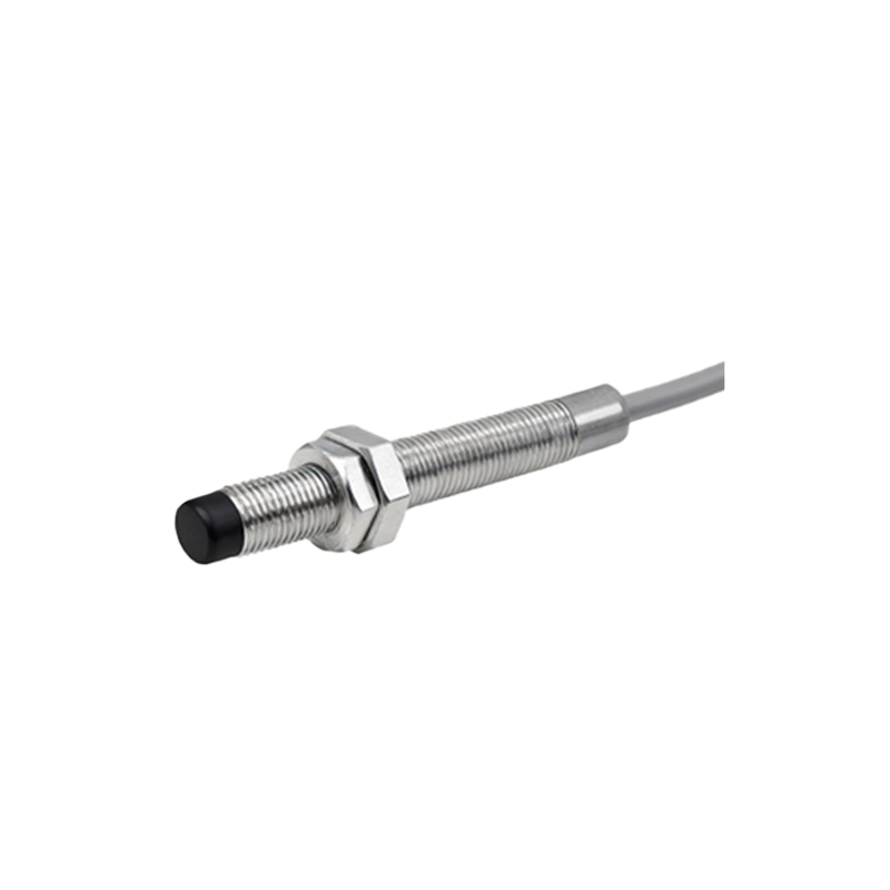
The primary objective of wiring sensors in series is to create a logical AND condition. The output circuit is completed only when all sensors in the series string are activated simultaneously. This is particularly useful in safety interlock systems or multi-stage verification processes where a machine sequence should only proceed if all monitored conditions are met. For instance, in a guarded machine, you might wire three door-position sensors in series so that the control system receives a "safe" signal only when all doors are securely closed.
Let's detail the wiring procedure for a series of PNP-type 3-wire sensors. First, connect the brown wires (V+) of all sensors to the positive terminal of the DC power supply. Similarly, connect all blue wires (0V) to the negative terminal or common ground of the supply. This establishes the power circuit for each sensor independently. The critical series connection is made with the output (black) wires. Connect the black wire of the first sensor to one terminal of your load (e.g., a PLC digital input). Then, instead of connecting the second sensor's black wire directly to the supply, connect it to the other terminal of the same load. This creates a path where the load receives power only if both Sensor 1 AND Sensor 2 are active, closing their internal switches to complete the circuit through the load. For more than two sensors, the concept extends by connecting the output wires in a daisy-chain fashion through the load.
For NPN sensors, the logic is similar but the current flow direction is reversed. All brown wires connect to V+, and all blue wires to 0V. The black (output) wire of the first sensor connects to the load. The other side of the load is then connected to the positive supply (V+), not to ground. The series connection is completed by linking the second sensor's black wire to the junction between the first sensor's black wire and the load. In this sinking configuration, the load is energized when all NPN sensors activate, providing a path to ground.
Several crucial factors must be evaluated to ensure a robust series connection. Voltage Drop is the most significant. Each active sensor in the series string introduces a small voltage drop across its internal switching element (typically a transistor). When multiple sensors are in series, these drops accumulate. If the total voltage drop approaches or exceeds the supply voltage minus the minimum operating voltage required by the load, the system will fail. Always consult the sensor datasheet for its saturation voltage (Vce(sat)) and calculate the total drop. Using a higher supply voltage (e.g., 24V DC) and ensuring the load has a wide operating voltage range can mitigate this issue.
Current Limitations must also be respected. The total current flowing through the series chain is limited by the sensor with the lowest maximum switching current. Exceeding this rating can damage the sensor's output transistor. Furthermore, the inrush current of the load (like a PLC input module) must be within the sensors' capabilities. Always verify the continuous and peak current ratings.
While series wiring creates a logical AND, it also introduces a single point of failure diagnostic challenge. If one sensor in the string fails or becomes inactive, the entire circuit opens. Troubleshooting requires checking each sensor individually to locate the fault. For critical applications, consider using sensors with diagnostic outputs or employing a PLC with individual input channels configured for software AND logic, which offers easier fault identification.
In conclusion, wiring 3-wire proximity sensors in series is a practical technique for implementing hardware-based AND logic in control circuits. Success hinges on using identical output types (all PNP or all NPN), meticulous attention to voltage drop and current ratings, and a clear understanding of the desired safety