In the realm of industrial automation and control systems, proximity switches stand as fundamental components for non-contact object detection. Among their critical operational parameters, the switching frequency—often referred to as the response frequency or operating frequency—is a key determinant of sensor performance in high-speed applications. This article delves into the principle behind the frequency specification of proximity sensors, explaining its significance, influencing factors, and practical implications.
At its core, a proximity switch detects the presence or absence of a target object without physical contact. Common types include inductive (for metallic targets), capacitive (for both metallic and non-metallic targets), and photoelectric sensors. Regardless of the sensing technology, the switching frequency defines the maximum number of switching cycles (from detection to non-detection and back) the sensor can reliably perform per second, typically measured in Hertz (Hz). A sensor rated at 1000 Hz, for instance, can theoretically detect up to 1000 objects passing by per second.
The principle governing this frequency is intrinsically linked to the sensor's internal oscillator, signal processing circuit, and output stage. Let's consider an inductive proximity sensor as a primary example. The sensor head contains a coil that generates a high-frequency electromagnetic field. When a metallic target enters this field, eddy currents are induced in the target, which dampens the oscillation amplitude of the coil's circuit. This change is detected by the sensor's evaluation circuitry.
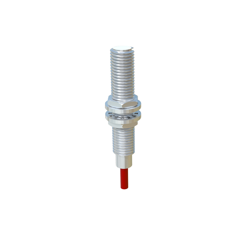
The journey from physical phenomenon to a clean output signal involves several time-critical stages:
1. Oscillator Stabilization & Damping Detection: The oscillator must operate at a stable frequency. The time required for the field to establish and for the damping effect to be conclusively recognized after a target enters the sensing range contributes to a delay.
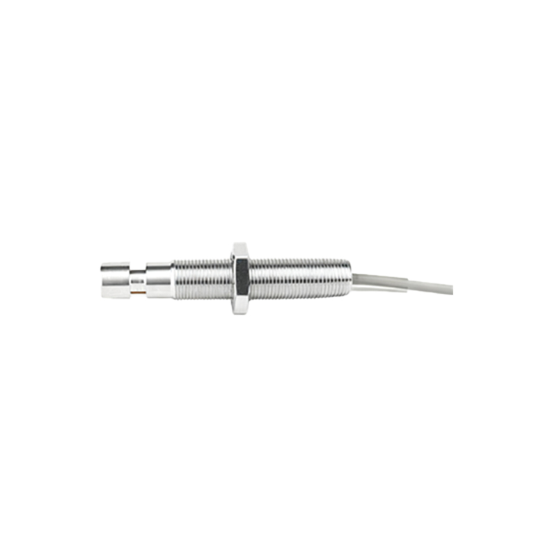
2. Signal Conditioning: The damped signal is weak and noisy. It must be amplified, filtered, and compared to a predefined threshold to make a definitive "target present" decision. The filtering and hysteresis circuits prevent false triggering but add a finite processing time.
3. Output Switching: The final electronic output (e.g., PNP/NPN transistor, solid-state relay) must physically switch state. Even fast-switching transistors have a non-zero rise and fall time (ton/toff). This switching time is often the most significant bottleneck for the maximum achievable frequency.
Therefore, the total response time of a sensor is the sum of the target approach time (dependent on sensing distance and target speed), the internal signal processing time, and the output switching time. The maximum switching frequency (f_max) is inversely proportional to the total response time (T_total), often approximated as f_max ≈ 1 / (2 T_total), accounting for both on and off cycles.
Several critical factors influence the practical switching frequency:
Sensor Technology: Inductive and capacitive sensors have inherent oscillator limitations. Photoelectric sensors, especially diffuse or through-beam types, often have much higher frequencies (up to several kHz) as they rely on light reception speed.
Sensing Distance: Operating a sensor very close to its nominal sensing range (Sn) can improve response time slightly. A larger air gap requires more time for the field to interact with the target.
Target Characteristics: For inductive sensors, the target's material, size, and shape matter. A standard mild steel target of sufficient size provides optimal conditions. Smaller or non-ferrous targets (like aluminum or copper) may reduce the effective sensing distance and can slightly alter the damping response time.
Output Configuration: Two-wire AC/DC sensors generally have lower switching frequencies than three-wire or four-wire DC models due to their need for a residual current to maintain function. Solid-state outputs (DC) are faster than relay outputs.
Environmental Conditions: Extreme temperatures, strong electromagnetic interference, or contamination on the sensor face can affect oscillator stability and signal integrity, indirectly impacting reliable switching frequency.
In application, exceeding the sensor's rated frequency leads to missed detections or erroneous signals. For example, on a high-speed bottling line or a packaging machine with rapidly moving items, selecting a sensor with insufficient frequency will result in counting errors. Engineers must calculate the required frequency based on the maximum object speed and the minimum object gap. The formula is typically: Required Frequency (Hz) = Object Speed (m/s) / Object Gap (m). A safety factor of 1.5 to 2 is usually applied to the calculated value.
Furthermore, the duty cycle is important. A sensor rated for 2000 Hz might sustain that rate only for short bursts. Continuous operation at the absolute maximum frequency can generate internal heat, potentially reducing the sensor's lifespan. Consulting the manufacturer's datasheet for detailed timing diagrams (response time vs. supply voltage, temperature, etc.) is essential for robust system design.
In conclusion, the switching frequency of a