In industrial automation and control systems, proximity sensors play a critical role in detecting the presence or absence of objects without physical contact. Among various wiring configurations, the 2-wire proximity sensor is widely adopted due to its simplicity and cost-effectiveness. This article provides a detailed guide on the 2-wire wiring diagram, installation practices, and key considerations for optimal performance.
A 2-wire proximity sensor integrates both power supply and signal output into two wires, simplifying installation compared to 3-wire or 4-wire types. Typically, these sensors operate on DC or AC voltage, with common ratings such as 10-30V DC or 20-250V AC. The wiring involves connecting one wire to the positive terminal (for DC) or live terminal (for AC) and the other to the load (e.g., a PLC input or relay). Since the sensor draws a small leakage current even when off, it’s essential to ensure the load impedance is within specified limits to avoid false triggering.
The wiring diagram for a 2-wire proximity sensor is straightforward. For DC sensors, connect the brown wire (usually positive) to the power supply’s positive terminal and the blue wire (negative) to the load’s input. The load’s other side links to the power supply’s negative terminal, forming a series circuit. In AC configurations, the brown wire connects to the live phase, and the blue wire to the load, with the load’s return path to the neutral line. Always refer to the manufacturer’s datasheet for color codes, as variations exist. A visual diagram typically shows the sensor in series with the power source and load, highlighting polarity requirements for DC models.
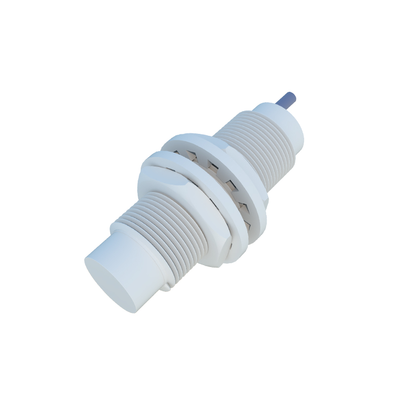
Installation requires attention to environmental factors. Mount the sensor securely, ensuring the sensing face is unobstructed and aligned correctly with the target object. Maintain adequate clearance from metal surfaces or other sensors to prevent interference. For inductive proximity sensors (common for metal detection), the sensing distance depends on the target material—steel provides the rated range, while non-ferrous metals reduce it. Capacitive sensors, used for non-metallic objects, may require calibration for material-specific sensitivity.
Key considerations include voltage drop and leakage current. Due to the series wiring, the sensor’s internal resistance causes a voltage drop across the load. Verify that the residual voltage at the load meets the minimum requirement for reliable operation, typically above 80% of the supply voltage. Leakage current (usually 1-2 mA) can accumulate in multi-sensor setups, potentially activating loads unintentionally. Use a bleeder resistor in parallel with the load if necessary, as per technical guidelines.
Troubleshooting common issues involves checking connections with a multimeter. If the sensor fails to trigger, measure voltage at the load terminals to confirm adequate supply. Ensure the target object is within the specified sensing range and material compatibility. For false signals, inspect for electrical noise from nearby motors or cables—shielded wiring and proper grounding often mitigate this. Regular maintenance, such as cleaning the sensor face from dust or oil, prolongs lifespan.
In summary, 2-wire proximity sensors offer a streamlined solution for many applications, from conveyor systems to safety interlocks. By following correct wiring diagrams and installation practices, engineers can enhance system reliability and efficiency. Always prioritize safety by disconnecting power during wiring and adhering to local electrical codes.