As an electrical engineer, integrating laser sensors with Arduino microcontrollers opens up a wide array of practical applications, from precision distance measurement to object detection systems. This experiment guide provides a step-by-step approach to setting up a basic laser sensor module with an Arduino board, focusing on operational principles, circuit design, and data interpretation.
Laser sensors, particularly those based on time-of-flight or triangulation principles, offer high accuracy for non-contact measurements. For this experiment, we will use a common laser distance sensor module, such as the VL53L0X, which communicates via I2C protocol. Begin by gathering components: an Arduino Uno or Nano, the laser sensor module, jumper wires, and a breadboard. Ensure the Arduino IDE is installed on your computer with necessary libraries, like the Adafruit_VL53L0X library, added to facilitate communication.
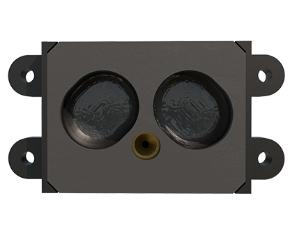
First, examine the sensor's pinout. Typically, it includes VCC (3.3V or 5V), GND, SDA (serial data), and SCL (serial clock). Connect VCC to the Arduino's 3.3V pin, GND to ground, SDA to analog pin A4 (or the dedicated SDA pin on some boards), and SCL to analog pin A5 (or SCL pin). Double-check connections to prevent short circuits, as improper wiring can damage components.
Next, power up the Arduino and upload a basic sketch. Start by including the Wire and sensor libraries. Initialize the sensor in the setup() function and set up serial communication for data output. In the loop() function, read distance values and print them to the serial monitor. For example, a simple code snippet might call sensor.readRange() to obtain measurements in millimeters. Observe the serial monitor at a baud rate of 9600; you should see real-time distance readings. If readings are erratic, verify connections and ensure the sensor is correctly initialized.
To enhance the experiment, consider environmental factors. Laser sensors can be affected by ambient light or reflective surfaces. Test in a controlled environment, and if needed, implement filtering in code, such as averaging multiple readings to reduce noise. Additionally, calibrate the sensor by comparing its output with a known distance using a ruler, adjusting offsets in the code if necessary.
For practical applications, integrate the sensor into larger systems. For instance, create a safety alarm that triggers when an object is within a certain range, or log data to an SD card for analysis. Engineers can expand this by adding multiple sensors for 3D mapping or combining with servos for scanning mechanisms. Always prioritize safety: avoid pointing the laser directly at eyes and use protective equipment when handling high-power modules.
Debugging is crucial. Common issues include I2C address conflicts—ensure no other devices share the same address—and power supply noise. Use oscilloscopes to check signal integrity if readings are unstable. Document your process, including schematic diagrams and code comments, to facilitate replication and troubleshooting.
In summary, this Arduino laser sensor experiment demonstrates fundamental skills in sensor integration, coding, and system design. It serves as a foundation for advanced projects in automation, robotics, and IoT, where precise measurement is key. Continuously explore datasheets and community resources to optimize performance and adapt to specific engineering challenges.