In the rapidly evolving landscape of industrial automation and precision measurement, laser distance sensors have become indispensable tools. Among the prominent names in this field, Muling laser distance sensors stand out for their robust performance, reliability, and adaptability across diverse applications. This guide delves into the core technology, operational principles, key application areas, and critical factors for selecting the right Muling sensor for your specific needs.
At its heart, a Muling laser distance sensor operates on the principle of time-of-flight (ToF) or phase-shift measurement. In the ToF method, the sensor emits a short pulse of laser light towards a target. The time taken for the reflected pulse to return to the sensor's receiver is precisely measured. Since the speed of light is a known constant, the distance to the target is calculated with high accuracy using the formula: Distance = (Speed of Light × Time of Flight) / 2. Phase-shift models, often used for even higher precision at shorter ranges, modulate the intensity of the laser beam. The distance is determined by measuring the phase difference between the emitted and reflected modulated signal. Muling sensors are engineered to perform these calculations rapidly and consistently, providing real-time, non-contact distance data.
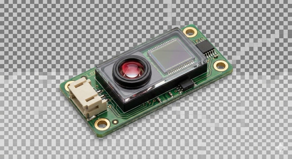
The construction of a typical Muling laser sensor involves several key components: a laser diode (usually Class 2, eye-safe), a high-sensitivity photodetector or position-sensitive device (PSD), precision optics for beam shaping and focusing, and a sophisticated microprocessor. This microprocessor handles signal processing, noise filtering, and output generation. Muling sensors are renowned for their rugged housing, often rated at IP67 or higher, making them resistant to dust, moisture, and mechanical shocks commonly found in industrial environments. They are designed to maintain measurement stability despite ambient light interference or variations in target surface color and texture, though highly reflective or absorbent surfaces may require specific calibration.
The application spectrum for Muling laser distance sensors is exceptionally broad. In industrial automation, they are pivotal for precise positioning, dimension checking, and height profiling on assembly lines. They control robotic arm trajectories, ensure correct fill levels in containers, and monitor the thickness of materials like rolled metal or paper. In the logistics and warehousing sector, these sensors facilitate palletizing, warehouse vehicle guidance, and inventory management through volume measurement. The construction industry leverages them for building profiling, alignment, and monitoring structural deformations. Furthermore, they are integral to agricultural automation for vehicle guidance and yield monitoring, and even in security systems for perimeter protection.
When selecting a Muling laser distance sensor, several technical parameters must be carefully evaluated. The measuring range is fundamental; it defines the minimum and maximum distances the sensor can accurately cover. The accuracy and resolution specify the smallest detectable distance change and the tolerance of the measurement, respectively. High-speed applications demand attention to the response time or measurement frequency. The laser spot size influences precision, especially on small targets. Output interfaces are crucial for system integration; common options include analog (4-20mA, 0-10V), digital (RS232, RS485, USB), and industrial fieldbus protocols (Profibus, EtherCAT). The choice depends on the existing control system architecture. Environmental ratings like IP code and operating temperature range ensure the sensor will survive its intended workspace.
Installation and maintenance are straightforward but vital for optimal performance. Ensure the sensor is mounted securely, with its optical axis perpendicular to the target surface under normal operating conditions. Avoid mounting near strong sources of vibration or heat. Keep the lens clean from dust, oil, or condensation, using only recommended cleaning materials. While Muling sensors are built for durability, periodic verification against a known reference distance is good practice to maintain long-term accuracy. Most models feature built-in diagnostics and status indicators to simplify troubleshooting.
Looking ahead, the future of Muling and similar laser sensing technology points toward even greater miniaturization, enhanced intelligence, and network integration. We can expect sensors with embedded IoT capabilities for predictive maintenance, advanced models that can classify materials or detect multiple objects simultaneously, and tighter integration with AI-driven vision systems. These advancements will further solidify the role of laser distance sensors as the eyes of automated systems.
In conclusion, Muling laser distance sensors represent a mature yet continuously improving technology that delivers critical data for automation, quality control, and safety. By understanding their operating principles, meticulously matching their specifications to the application requirements, and following proper installation guidelines, engineers and system integrators can unlock significant gains in efficiency, precision, and operational reliability across countless industries.