Proximity sensors are indispensable components in modern industrial automation, providing non-contact detection of objects within their sensing range. Proper installation is critical to ensuring optimal performance, reliability, and longevity. Unlike many other sensors, proximity sensors are highly sensitive to their surrounding environment, mounting conditions, and target characteristics. Incorrect installation can lead to reduced sensing distance, false triggering, or even permanent damage. This article outlines the fundamental installation methods, key considerations, and industry best practices for inductive, capacitive, and magnetic proximity sensors commonly used in manufacturing and machinery.
The first and most crucial step is selecting the correct mounting style. Flush-mountable and non-flush-mountable (also known as shielded and unshielded) are the two primary designs for inductive and capacitive sensors. Flush-mountable sensors can be installed embedded in metal without affecting their sensing range, as their magnetic or electrostatic field is concentrated at the front face. They are ideal for tight spaces and applications where the sensor must be protected from mechanical damage. Non-flush-mountable sensors offer a longer sensing range but require a clearance zone around the sensing face—typically one to two times the sensor diameter—free of any surrounding metal. Installing a non-flush sensor flush with metal will drastically reduce its effective range.
Mounting hardware and alignment are equally important. Sensors should be securely fastened using appropriate brackets, nuts, or mounting clamps to prevent vibration-induced movement or misalignment. Even slight shifts can cause inconsistent detection. The sensing face must be positioned parallel to the target surface for maximum efficiency. For cylindrical barrel sensors, standard threaded metal or plastic housings (e.g., M8, M12, M18, M30) are used, and it is vital to avoid overtightening, which can distort the housing and affect performance. Always follow the manufacturer's specified torque values. For block-style sensors, ensure the mounting holes align correctly and use all provided fasteners.
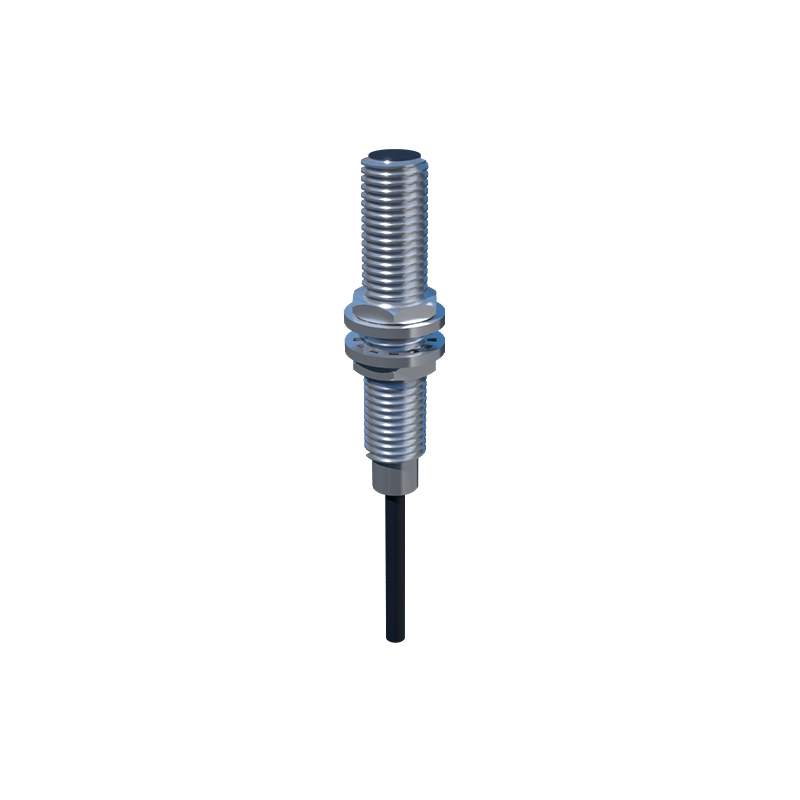
Environmental factors play a significant role in installation planning. For inductive sensors, which detect metallic objects, ensure that no moving metal parts other than the target pass within the sensor's field, as this can cause interference. Capacitive sensors, sensitive to both conductive and non-conductive materials, can be affected by humidity, dust, or contaminants on the sensing surface. In such conditions, consider installing a protective cover or choosing a sensor with an environmental resistance rating (IP67 or higher). Always maintain the recommended temperature range and avoid direct exposure to cutting fluids, oils, or strong chemicals unless the sensor is specifically rated for such exposure.
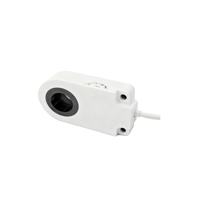
Wiring and electrical connections must adhere to safety standards and sensor specifications. Most proximity sensors operate on DC (10-30V DC) or AC voltages and feature three-wire or two-wire configurations. Use shielded cables in electrically noisy environments, such as those near variable frequency drives (VFDs) or welding equipment, and ground the shield properly at the control panel. Keep signal cables separate from power lines to minimize electromagnetic interference. For DC sensors, pay close attention to polarity (brown wire to positive, blue to negative) and load connection. The load (e.g., PLC input, relay) should be connected between the output wire (usually black) and the positive supply. Incorrect wiring can damage the sensor's output circuit.
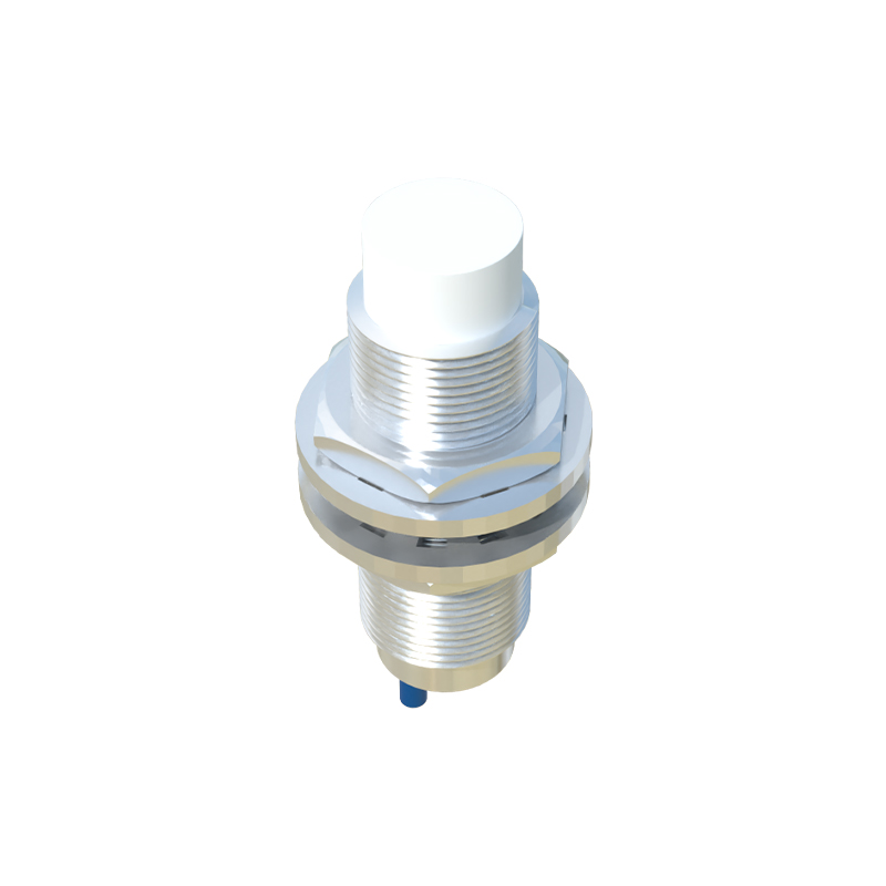
Target characteristics must match the sensor's specifications. The sensing distance listed in datasheets is based on a standard target (often mild steel for inductive sensors). For other materials, a correction factor must be applied; for instance, sensing distance for stainless steel is typically 70-90% of the rated value, and for aluminum or copper, it can be as low as 30-50%. The target size should be at least equal to the sensor's sensing face diameter for reliable detection. For small targets, reduce the effective sensing distance accordingly. Additionally, ensure the target approaches the sensor head perpendicularly for consistent operation; angular approaches can reduce the effective sensing range.
Finally, after installation, thorough testing under actual operating conditions is mandatory. Verify the sensor triggers consistently at the required distance with all intended target materials. Check for interference from adjacent machinery, sensors, or metal structures. Many modern sensors feature LED indicators for output status, which are invaluable for diagnostics. Implement regular maintenance schedules to clean the sensing face, check mounting integrity, and inspect cables for wear. By meticulously following these installation guidelines—selecting the proper mount type, securing alignment, managing environmental and electrical factors, matching target specs, and validating performance—engineers can ensure proximity sensors deliver precise, reliable detection, thereby enhancing system uptime and operational safety in demanding industrial environments.