In the realm of precision measurement and industrial automation, laser displacement sensors have become indispensable tools. Their ability to provide non-contact, high-accuracy measurements of distance, thickness, and vibration is critical for quality control, process monitoring, and robotic guidance. While specifications like resolution, linearity, and measurement range are often the primary focus during sensor selection, the frequency response is a parameter of paramount importance for dynamic or high-speed applications. This article delves into the concept of frequency response in laser displacement sensors, its technical underpinnings, and its practical implications for system performance.
Fundamentally, the frequency response of a sensor describes how its output signal behaves when the measured target is moving or vibrating at varying frequencies. It quantifies the sensor's ability to accurately track rapid changes in position. Technically, it is a measure of the amplitude attenuation and phase shift of the output signal relative to the true displacement of the target across a spectrum of frequencies. A sensor with a high-frequency response can faithfully reproduce high-speed movements, while one with a lower response will smooth out or completely miss high-frequency components, leading to measurement error.
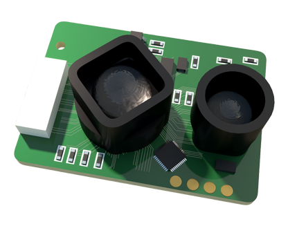
The frequency response is typically characterized by the -3 dB bandwidth. This is the frequency at which the sensor's output signal amplitude falls to approximately 70.7% of its low-frequency, or DC, value. For instance, a sensor with a stated frequency response of 50 kHz can accurately measure vibrations or displacements with frequency components up to 50 kHz before the signal becomes significantly attenuated. Beyond this point, the measurement data loses fidelity. It is crucial to understand that this bandwidth is not solely determined by the laser or optical system. The entire signal chain contributes, including:
1. Detector Response Time: The photodetector (e.g., a Position Sensitive Detector (PSD) or CMOS/CCD array) has a finite speed at which it can convert incident light into an electrical signal.
2. Signal Processing Electronics: The analog circuitry and digital algorithms (filters, amplifiers, analog-to-digital converters) used to condition the detector's output impose significant limits. The design of these filters—often low-pass filters to reduce noise—directly defines the system's bandwidth.
3. Output Interface: The chosen output method, such as analog voltage/current or digital communication (EtherCAT, PROFINET, RS-422), has its own update rate or cycle time. A high internal bandwidth is futile if the digital output only updates at 1 kHz; the effective system bandwidth is then capped at 1 kHz.
In practical terms, selecting a sensor with an appropriate frequency response is critical. Consider these application scenarios:
* Vibration Analysis on Motors or Bearings: To diagnose faults, you must capture high-frequency vibration spectra. A sensor with a 10 kHz bandwidth might miss critical harmonics indicating bearing wear, whereas a 100 kHz sensor would capture them.
* High-Speed Eccentricity Measurement of Rotating Shafts: The rotational speed and any out-of-roundness defects create periodic displacement. The sensor bandwidth must be several times higher than the fundamental rotational frequency and its expected harmonics.
* Control of Fast-Actuating Systems: In closed-loop servo control for precision stages or active damping systems, the sensor acts as the system's "eyes." A slow sensor (low bandwidth) introduces phase lag, which can destabilize the control loop, leading to oscillations or poor performance.
* Thickness Measurement of Moving Webs: While web speed might be constant, flutter, tension variations, and material inconsistencies introduce higher-frequency noise. A sensor must have sufficient bandwidth to average these out accurately without aliasing.
A common pitfall is underestimating the required bandwidth. A good rule of thumb is that the sensor's -3 dB bandwidth should be at least 5 to 10 times higher than the highest frequency component of interest in the target's motion. This ensures minimal amplitude distortion and phase delay. Furthermore, the sampling theorem must be respected: the sensor's sampling rate (for digital models) must be more than twice the highest frequency component to avoid aliasing, where high-frequency signals appear as erroneous low-frequency data.
It is also vital to distinguish between small-amplitude and large-amplitude frequency response. Many datasheets specify bandwidth for a very small displacement (e.g., ±0.1 mm). The effective bandwidth can decrease significantly when tracking larger amplitudes because the internal electronics or detector may have slew rate limitations. Always consult the manufacturer's detailed specifications or application engineers for demanding large-signal dynamic measurements.
Environmental factors and setup can also degrade effective frequency response. Reflections from glossy surfaces, varying surface colors (affecting light intensity), and mechanical mounting vibrations can introduce noise that masks the true signal, effectively reducing the usable signal-to-noise ratio at higher frequencies.
In conclusion, the frequency response is a key dynamic performance metric for laser displacement sensors, as critical as static accuracy. Engineers must move beyond looking solely at resolution and linearity. By understanding the factors that limit bandwidth—from detector physics to digital interfaces—and by carefully analyzing the spectral content of the target motion, one can select a sensor that ensures reliable, high-fidelity data. This enables robust high-speed inspection, precise dynamic control, and accurate diagnostic monitoring, unlocking the full potential of automation in modern manufacturing and R&D environments. Always prioritize a system-level view, ensuring the sensor's dynamic capabilities are matched to the demands of the entire measurement or control system.