Proximity sensors are indispensable components in modern industrial automation, providing non-contact detection of metallic or non-metallic objects. A critical aspect of ensuring their reliable operation is the correct wiring of the sensor connector. Incorrect wiring can lead to sensor malfunction, equipment damage, or even safety hazards. This guide details the standard wiring sequences for common proximity sensor connectors, focusing on both 3-wire and 4-wire DC configurations prevalent in industrial settings.
Most industrial proximity sensors operate on DC voltage, typically 10-30V DC. The three-wire DC sensor is the most common. Its connector usually houses three wires distinguished by color coding: brown, blue, and black. The brown wire is universally designated for the positive supply voltage (+V). The blue wire is always connected to the common negative or ground (0V). The black wire is the signal output line. For a normally open (NO) sensor, the black wire provides a switched positive voltage when a target is detected. For a normally closed (NC) type, the voltage on the black wire drops to near zero upon detection. Some manufacturers use white or gray wires for a second output or a complementary signal. It is paramount to consult the specific sensor's datasheet, as wire colors can occasionally vary by brand or region.
Four-wire DC sensors add an additional output, allowing for both NO and NC functions from a single device. The standard color scheme often extends to include both black and white wires. Typically, brown remains +V, blue is 0V, black is the NO output, and white is the NC output. Again, verification against manufacturer documentation is essential. The wiring sequence must align with the mating connector on the programmable logic controller (PLC) input module or the intermediary junction box. Most PLC sink/source input cards have clearly labeled terminals for DC Common, +V, and input channels.
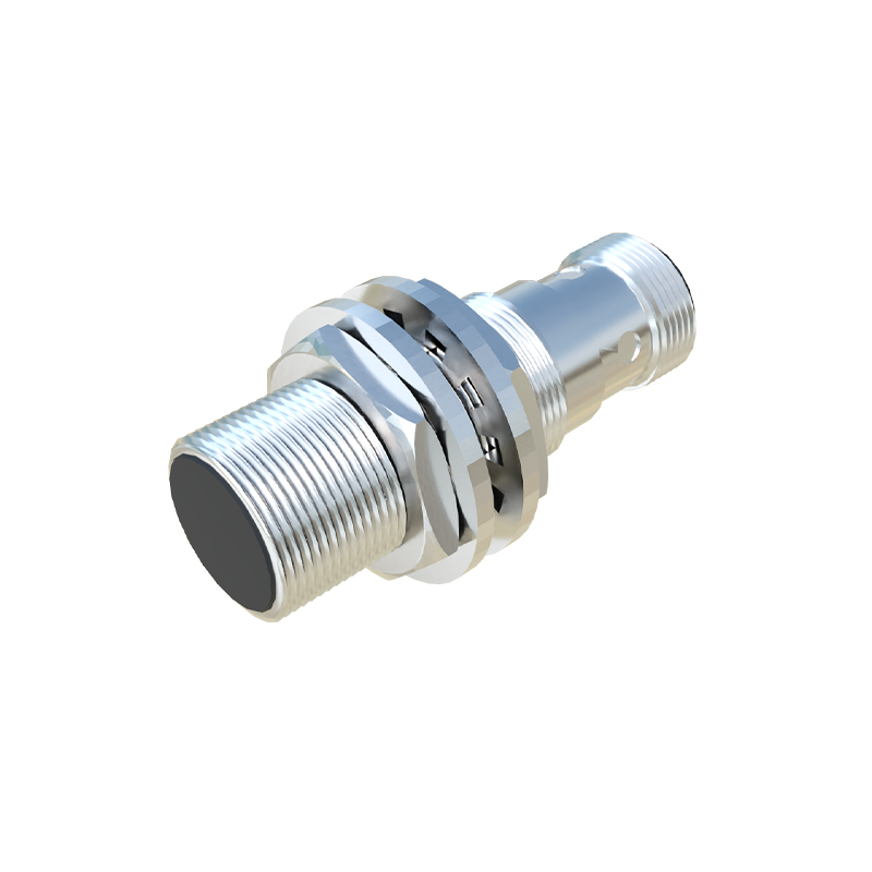
For connector types, M8 and M12 circular connectors with 3 or 4 pins are the industry norm, offering IP67-rated environmental protection. The pin numbering is standardized. In a 3-pin M12 connector, pin 1 is typically for +V (brown), pin 2 is for output (black), and pin 3 is for 0V (blue). In a 4-pin version, pin assignments might be: 1: +V (brown), 2: Output 1 (black), 3: Output 2 (white), 4: 0V (blue). Some sensor families, particularly those from certain European manufacturers, may use a reverse coding where pin 1 is 0V. This underscores the non-negotiable practice of checking pin diagrams.
Shielded cable is recommended for installations in electrically noisy environments. The cable shield should be grounded at the control panel end only to prevent ground loops. When wiring, ensure proper strain relief and that the connector is securely locked to its receptacle. A loose connection can cause intermittent failures. For maintenance, always isolate power before disconnecting sensors.
Troubleshooting often starts with verifying the wiring sequence. A multimeter can check for the presence of supply voltage between brown and blue wires. With a target present, the voltage between the black output wire and blue wire should switch state. If the sensor fails, do not overlook the possibility of a wiring sequence error, a mismatched PLC input type (sourcing vs. sinking), or an incorrect load connected to the output.
In summary, adhering to the correct wiring sequence—brown (+V), blue (0V), black (output)—forms the foundation of a robust sensor network. Always cross-reference color codes with pin numbers using official manuals. This disciplined approach minimizes downtime and ensures the precision required for automated systems in manufacturing, packaging, and material handling applications.