In industrial automation and control systems, integrating sensing devices with indicator lights is a fundamental task for providing visual feedback. A common application involves connecting a 24V DC proximity sensor to illuminate a pilot light or warning lamp. This setup is crucial for machine operators to quickly verify sensor activation, detect part presence, or identify process status. The 24V DC standard is widely preferred in factory environments due to its safety, noise immunity, and compatibility with Programmable Logic Controllers (PLCs). This article provides a detailed, step-by-step guide on correctly wiring a 3-wire DC proximity sensor to a light, ensuring reliable and safe operation.
First, it is essential to understand the basic components and their functions. A typical 3-wire DC proximity sensor has three connection points: brown wire for positive DC supply (+24V), blue wire for the common negative or DC 0V, and a black wire which is the switched output signal. The load, in this case an indicator light, must be rated for 24V DC operation. LED lamps are highly recommended for their long lifespan, low power consumption, and durability. Ensure the sensor's output type matches your circuit design; it can be either NPN (sinking) or PNP (sourcing). This guide will cover the wiring for both configurations, as the connection method differs significantly.
For a system using a PNP-type proximity sensor, the black output wire acts as a switched positive source. Begin by connecting the sensor's brown wire to the +24V DC power supply terminal. Connect the sensor's blue wire to the 0V or negative terminal of the same power supply. The PNP sensor's output (black wire) will supply +24V when it detects a target. Therefore, one terminal of the 24V lamp should be connected to this black wire. The other terminal of the lamp must then be connected to the 0V (common negative) of the power supply. This completes the circuit. When the sensor activates, current flows from the sensor's output, through the lamp, and back to the power supply's negative, causing the light to turn on.
In contrast, wiring an NPN-type sensor requires a different approach. The NPN sensor's black wire acts as a switched negative or sinking output. As with the PNP, connect the brown wire to +24V and the blue wire to 0V. However, for the lamp to illuminate, current must flow into the sensor's output. To achieve this, connect one terminal of the 24V lamp directly to the +24V supply rail. Connect the other terminal of the lamp to the sensor's black output wire. In this configuration, when the sensor detects an object, it internally connects the black wire to 0V, completing the circuit to ground. This allows current to flow from +24V, through the lamp, through the sensor's sinking output, and back to the power supply's negative, thereby illuminating the light.
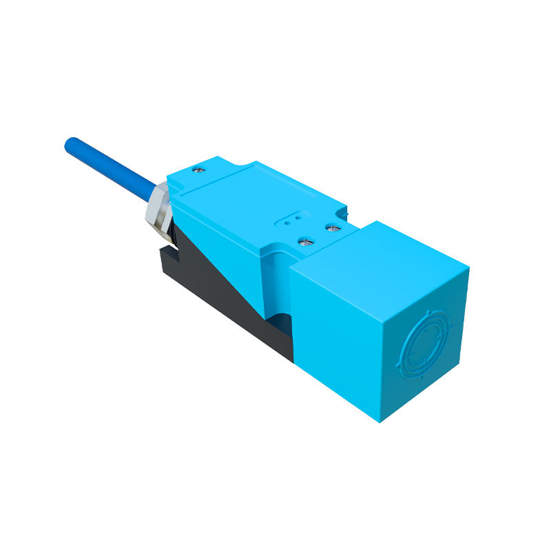
Safety and best practices are paramount. Always de-energize the control circuit before starting any wiring work. Use appropriate wire gauges; for typical sensor and lamp loads, 18-22 AWG stranded copper wire is sufficient. Implement proper fusing or circuit protection on the +24V supply line to protect against short circuits. Secure all connections using terminal blocks or crimp connectors to prevent loose wires, which are a common cause of failure. It is also advisable to include a protective flyback diode across the lamp terminals if it is an inductive load (like a small relay coil), though most modern LED indicators are purely resistive. Finally, verify the sensor's sensing range and alignment to ensure it triggers reliably for the intended target material.
Troubleshooting is often straightforward if the light fails to operate. First, confirm power is present at the sensor by checking for 24V between the brown and blue wires with a multimeter. Next, verify the sensor's output state. With a target present, measure the voltage between the black wire and the blue wire (for PNP) or between the black wire and the brown wire (for NPN). A correct reading should show near 24V when active. If the sensor is functioning but the lamp is off, check the lamp's connections and continuity. Ensure the lamp itself is not burnt out by testing it with a known good 24V source. By methodically checking each part of the circuit—power supply, sensor, wiring, and load—you can quickly isolate and resolve any issues.
This wiring technique forms the basis for more complex automation indicators. The same principle can be extended to connect the sensor output to a PLC input module while simultaneously driving a lamp for local indication, often requiring an interposing relay or an isolated output module to handle both loads. Understanding how to interface a 24V proximity sensor with a