In the realm of industrial automation and electrical engineering, proximity switch sensors are indispensable components for detecting the presence or absence of objects without physical contact. These sensors are widely used in machinery, conveyor systems, and safety applications, offering reliability and precision. When it comes to electrical schematics, accurately representing these devices is crucial for clear communication and error-free installation. Among the various types, three-wire proximity switches are particularly common due to their balanced performance and ease of integration. This article delves into the three-wire symbol for proximity switch sensors, explaining its significance, components, and practical implications in circuit design.
The three-wire proximity switch typically consists of three distinct wires: one for power supply, one for ground, and one for the output signal. In electrical schematics, this is represented by a standardized symbol that conveys essential information at a glance. The symbol generally includes a graphical icon resembling a switch or sensor, often depicted as a circle or rectangle with internal markings, accompanied by three connection points labeled accordingly. The power wire (usually denoted as V+ or +V) provides the operating voltage, commonly 12-24 V DC in industrial settings. The ground wire (GND or 0V) completes the circuit, ensuring stable operation. The output wire (OUT or NO/NC for normally open/normally closed) carries the signal indicating the sensor's state—active or inactive.
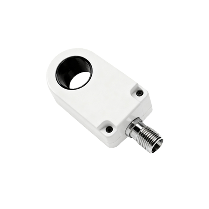
Understanding this symbol is vital for engineers and technicians because it directly impacts circuit functionality and safety. For instance, misinterpreting the output type (e.g., confusing a normally open with a normally closed configuration) can lead to system failures or hazardous conditions. In schematics, the three-wire symbol may also incorporate additional annotations, such as the sensing range (e.g., 5mm) or material detection (e.g., metallic objects for inductive sensors). This level of detail helps in selecting compatible components and designing efficient control systems.
From a practical perspective, the three-wire design offers advantages over two-wire versions, such as lower leakage current and better signal integrity, making it a preferred choice in many applications. When interpreting schematics, professionals must also consider the sensor's technology—inductive, capacitive, or optical—as this influences the symbol's context. For example, an inductive proximity switch symbol might include a coil-like element, while a capacitive one could show a plate representation. However, the core three-wire structure remains consistent, emphasizing universal principles in electrical documentation.
In conclusion, mastering the three-wire symbol for proximity switch sensors enhances schematic readability and promotes best practices in electrical engineering. By recognizing its components and implications, engineers can ensure robust system design and seamless maintenance. As automation evolves, this knowledge remains foundational for innovation and safety in industrial environments.