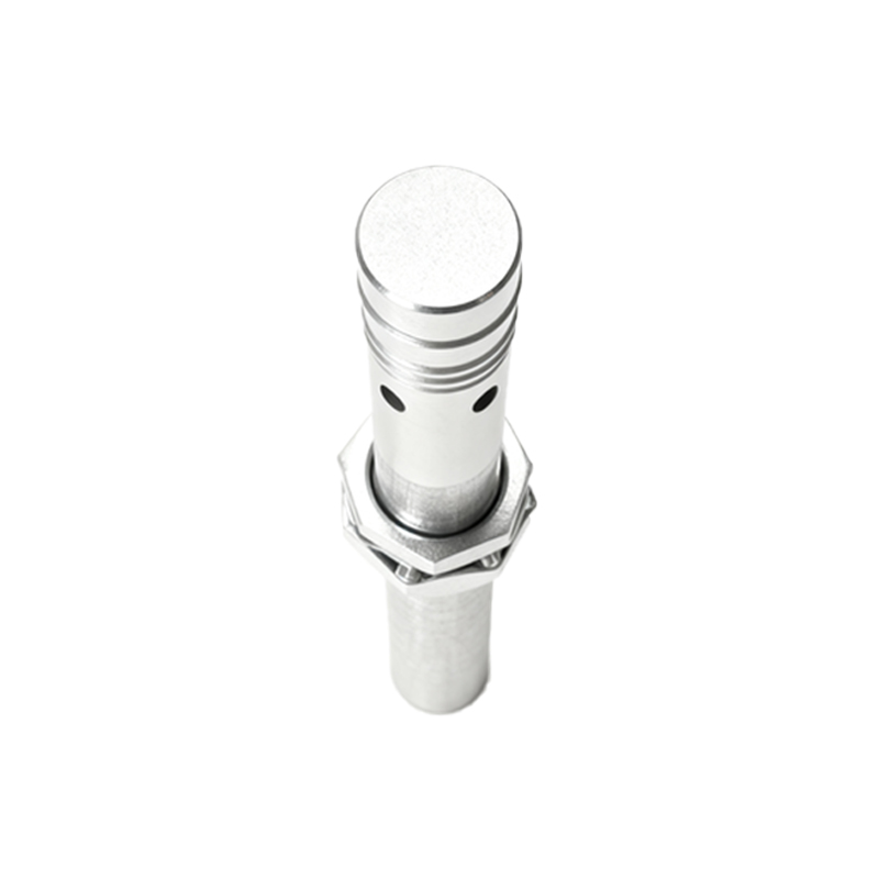
Proximity sensor lights, integral to modern automated lighting systems, occasionally fail to illuminate despite detected motion or presence. This malfunction, often a point of frustration, stems from a finite set of potential causes within the electrical and electronic chain. For engineers and technical personnel, a systematic diagnostic approach is essential for efficient resolution. The primary failure domains typically involve power supply integrity, sensor functionality, load compatibility, control circuitry, and environmental interference.
The initial and most critical checkpoint is the power supply. Verify the input voltage at the sensor's terminals matches the specified rating (e.g., 120VAC, 24VDC) using a multimeter. Fluctuations or complete absence of power will obviously prevent operation. Do not overlook the simple step of checking circuit breakers or fuses in the associated panel. For hardwired units, ensure all wire terminations are secure; loose connections are a prevalent cause of intermittent or total failure. In battery-operated wireless sensors, depleted batteries are the most common culprit and should be replaced as a first step.
Assuming stable power, the focus shifts to the proximity sensor itself. These sensors—whether Passive Infrared (PIR), ultrasonic, microwave, or capacitive—have specific detection ranges and fields of view. A sensor may be functional but misaligned, aimed at an area with insufficient motion or obstructed by new fixtures, furniture, or accumulated debris. The sensor's sensitivity and time delay settings must also be verified. If adjustable, a sensitivity set too low may ignore valid triggers, while an excessively long time delay might keep the light off if it hasn't yet reset from a prior activation. Internal sensor failure, while less common, is possible. Testing involves bypassing the sensor control: temporarily connecting the load (the light fixture) directly to the line power. If the light operates normally, the fault likely lies with the sensor or its control relay.
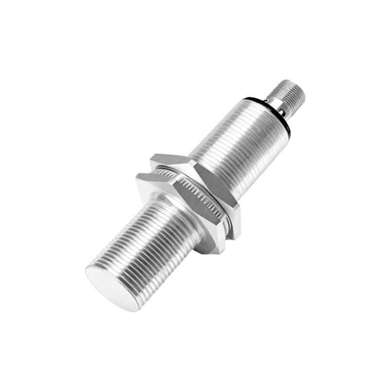
The load, or the connected lighting fixture, is the next component for evaluation. Even with a correct signal from the sensor, a faulty lamp (LED array, bulb, or ballast) will not illuminate. Perform a direct power test to the fixture as described. Furthermore, verify the load's wattage or current draw does not exceed the sensor's rated maximum capacity. Overloading a sensor can damage its internal switching mechanism, often a relay or solid-state switch. For LED fixtures, compatibility is crucial. Some older sensor models may not function correctly with low-wattage LED loads due to minimal current draw, causing unreliable switching. Using a resistive "dummy load" or selecting a sensor explicitly designed for LED compatibility can resolve this.
The control circuitry within the sensor housing warrants inspection. Modern sensors incorporate photocells (daylight sensors) to prevent activation during sufficient ambient light. A failed or overly sensitive photocell will inhibit the sensor regardless of motion. Many units have a photocell override function for testing; consult the manufacturer's datasheet. Additionally, inspect the internal electronics for signs of thermal damage, capacitor bulging, or burnt components, which indicate failure due to power surges, moisture ingress, or prolonged overload.
Environmental factors are a significant and sometimes overlooked cause. Radio Frequency Interference (RFI) from nearby industrial equipment, high-power transmitters, or even variable frequency drives can disrupt the sensitive electronics of a proximity sensor, causing erratic behavior or lock-up. Extreme temperatures, outside the sensor's specified operating range, can also cause failure. Condensation or direct water ingress, particularly in outdoor or washdown environments, will lead to corrosion and short circuits. Ensure the sensor's Ingress Protection (IP) rating is suitable for its installation location.
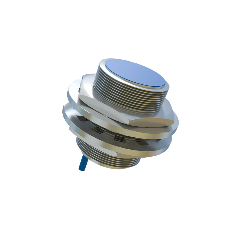
Finally, review the installation against the manufacturer's guidelines. Ensure the sensor type is appropriate for the application (e.g., a PIR sensor for detecting people in a corridor, an ultrasonic sensor for detecting minor motion in a room). The mounting height and angle are critical for optimal coverage. Wiring errors, such as swapping line and load connections or incorrect neutral handling in 3-wire systems, will prevent operation. Always reference the specific wiring diagram provided.
A logical, step-by-step process—from verifying primary power to assessing environmental conditions—will isolate the fault in the vast majority of cases. Documenting findings and solutions contributes to a knowledge base for future troubleshooting, enhancing system reliability and operational uptime.