Proximity sensors are indispensable components in modern industrial automation, robotics, and machinery. Their ability to detect the presence or absence of an object without physical contact makes them reliable, durable, and versatile. Understanding how to use them correctly is crucial for ensuring system efficiency, safety, and longevity. This guide provides a detailed overview of proximity sensor usage, from selection to installation and troubleshooting.
1. Understanding Proximity Sensor Types

The first step in proper usage is selecting the correct sensor type for your application. The primary categories are:
Inductive Proximity Sensors: Detect metallic objects (ferrous and non-ferrous). They generate an electromagnetic field. When a metal object enters this field, it induces eddy currents, causing a change in oscillation amplitude that is detected by the sensor circuit. Ideal for machine tools, automotive assembly, and metal detection.
Capacitive Proximity Sensors: Can detect both metallic and non-metallic materials (plastics, wood, liquids, granules) by measuring changes in capacitance. They sense changes in the dielectric constant between the sensor's face and the target. Commonly used in level detection, material handling, and presence sensing of non-metals.
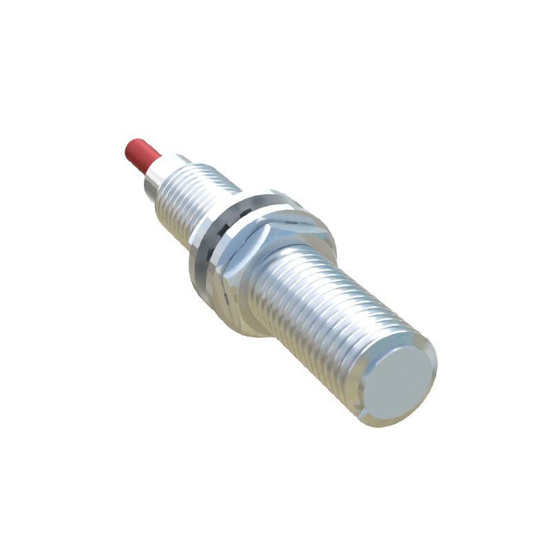
Ultrasonic Proximity Sensors: Use sound waves to detect objects and measure distance. They emit high-frequency sound pulses and calculate the time for the echo to return. Effective for clear object detection, liquid level control, and applications requiring precise distance measurement, regardless of color or material.
Photoelectric Sensors: Use a light beam (visible, infrared, or laser) to detect objects. They come in through-beam, retro-reflective, and diffuse-reflective modes. Excellent for long-range detection, small object sensing, and transparent material detection.
2. Key Steps for Proper Installation and Use
Correct installation is paramount for optimal performance.
Mounting: Ensure secure mounting to prevent vibration-induced errors. Maintain the specified sensing distance. For inductive and capacitive sensors, be mindful of the "flush-mountable" or "non-flush" design. Flush-mounted sensors can be embedded in metal without affecting performance, while non-flush sensors offer longer ranges but require a clear surrounding area.
Sensing Distance: Always refer to the datasheet for the "rated operating distance (Sn)." Account for factors like target material, size, and temperature, which can affect the actual sensing distance. A standard practice is to use 70-80% of the rated distance to ensure reliability.
Wiring and Connections: Follow the manufacturer's wiring diagram meticulously. Most sensors have three wires: Brown (V+), Blue (V- or Common), and Black (Output). For DC sensors, ensure correct polarity. Connect the load (e.g., PLC input, relay) in series with the output wire. Use shielded cables in electrically noisy environments and ground the shield properly at one end.
Environment Considerations: Protect sensors from physical damage, excessive heat, coolant, oil, or dust. Select sensors with appropriate IP (Ingress Protection) ratings (e.g., IP67 for dust-tight and temporary immersion). For inductive sensors, avoid mounting opposite each other to prevent mutual interference.
3. Configuration and Adjustment
Many sensors require fine-tuning.
Sensitivity Adjustment: Capacitive sensors often feature a potentiometer to adjust sensitivity for different materials. Adjust until the sensor reliably detects the target without false triggering from background objects.
Response Time: Set the sensor's response time appropriately for your application speed. A faster response time is needed for high-speed production lines.
Output Configuration: Configure the output type (Normally Open NO / Normally Closed NC) and mode (discrete switch, analog, or IO-Link) to match the control system's requirements.
4. Integration with Control Systems
The sensor's output signal must be correctly interpreted by a controller like a PLC (Programmable Logic Controller).
Discrete (Digital) Sensors: Provide a simple ON/OFF signal. Connect the output to a PLC's digital input module. Ensure the voltage levels (e.g., 24V DC) are compatible.
Analog Sensors: Provide a continuous signal (e.g., 4-20mA, 0-10V) proportional to the distance. Connect to an analog input module for tasks like precise positioning or thickness measurement.
Networked Sensors (IO-Link): Offer advanced diagnostics, parameterization, and process data exchange over a standard 3-wire cable, simplifying setup and maintenance.
5. Common Troubleshooting Practices
Even with proper installation, issues may arise.
No Output Signal: Check power supply voltage and polarity. Verify wiring connections. Ensure the target is within the sensing range and is of the correct