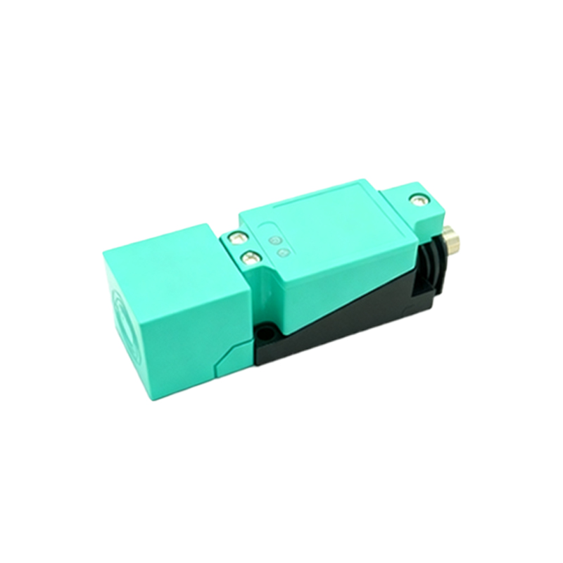
Inductive proximity sensors are non-contact electronic devices designed to detect the presence or absence of metallic objects without physical contact. Operating on the principle of electromagnetic induction, these sensors generate an oscillating electromagnetic field from a coil located at their sensing face. When a conductive metal target enters this field, eddy currents are induced on the target's surface, causing a change in the oscillation amplitude or frequency within the sensor's internal circuit. This change is detected and processed by the sensor's electronics, triggering a solid-state output signal—typically a switching action—to indicate object detection.
A key advantage of inductive sensors is their robustness. Encased in housing materials like nickel-plated brass, stainless steel, or PBT plastic, they are highly resistant to environmental challenges such as dust, oil, coolant, and vibration, making them ideal for harsh industrial settings like machining, material handling, and automotive assembly lines. Their non-contact nature eliminates mechanical wear, ensuring long operational life and minimal maintenance.
When selecting an inductive proximity sensor, several technical parameters must be considered. Sensing range, specified by the manufacturer, defines the maximum distance at which a standard target can be reliably detected. It is crucial to note that this range varies with the target material; for instance, steel is detected at the nominal range, while non-ferrous metals like aluminum or copper may reduce the effective sensing distance due to lower permeability and conductivity. Factors such as target size, shape, and orientation also influence performance. A flat, square steel target equal to or larger than the sensor's sensing face diameter, positioned axially, provides optimal detection.
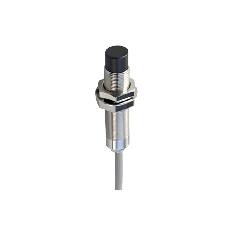
Output configurations are another critical selection factor. Common types include NPN (sinking) and PNP (sourcing) transistor outputs in DC versions, as well as AC/DC two-wire models. NPN outputs switch the negative (0V) line to the load, while PNP outputs switch the positive voltage line. The choice depends on the control system's PLC or controller input card requirements. Additionally, sensors come in normally open (NO) or normally closed (NC) switching logic. Housing styles are diverse, including cylindrical threaded barrels (e.g., M8, M12, M18, M30), rectangular, and slot styles, allowing for flexible mounting in confined spaces.
Installation and application require attention to detail. Sensors should be mounted securely to avoid vibration-induced false signals. In metallic environments, maintaining a minimum clearance between the sensor face and surrounding metal (mounting nut or machine frame) is essential to prevent electromagnetic field interference, known as the "flush-mountable" or "non-flush" characteristic. For demanding applications involving different metals, sensors with factor-1 capability (equal sensing range for all metals) are available, though typically at a higher cost.
Regular functional testing ensures reliability. A simple method involves using a metal target to verify the sensor's LED indicator and output signal. Troubleshooting often involves checking power supply voltage, wiring connections, and load compatibility. Understanding these fundamentals empowers engineers and technicians to effectively integrate inductive proximity sensors, enhancing automation system precision, safety, and efficiency.