In the high-precision world of industrial laser cutting, sensors play a critical role in ensuring operational accuracy, material handling, and overall system safety. These components, including capacitive height sensors, photoelectric sensors, and vision systems, are the eyes and nerves of the machine. However, exposure to intense heat, metal dust, fumes, and mechanical vibrations makes them prone to failure. Effective maintenance and skilled repair are not merely cost-saving measures; they are essential for minimizing costly downtime and maintaining cut quality. This guide provides a systematic approach to diagnosing, maintaining, and repairing common laser cutting sensor issues.
The first step in any repair process is accurate diagnosis. Symptoms of a failing sensor can manifest in various ways. Inconsistent cutting height, often resulting in poor edge quality or nozzle crashes, frequently points to a malfunctioning capacitive height sensor. Uncommanded process stops or failures in material detection typically indicate problems with photoelectric or proximity sensors. A thorough diagnostic procedure begins with a visual inspection. Examine the sensor lens or sensing face for accumulated debris, spatter, or physical damage. Even a thin layer of oxide dust can scatter a laser beam or interfere with a capacitive field. Carefully clean optical components using approved lens cleaners and lint-free wipes. For non-optical sensors, check for metallic buildup.
Next, verify the electrical connections. Vibration can loosen connectors, leading to intermittent signals. Inspect the wiring for signs of fraying, heat damage, or cuts, particularly in cable carriers. Use a multimeter to check for proper voltage supply at the sensor connector as per the manufacturer's datasheet. A simple output test can be performed: activate the sensor (e.g., by placing metal near a proximity sensor) and measure the output signal with a meter or oscilloscope to see if it switches correctly. For height sensors, many systems have a diagnostic screen showing the real-time analog signal; erratic readings here suggest sensor instability.
If basic checks do not resolve the issue, consult the machine's error logs. Modern CNC controllers record detailed alarms that can pinpoint which sensor channel is faulting. Cross-reference this with the system's electrical schematic to understand the sensor's integration. Environmental factors are often overlooked. Strong ambient light can blind photoelectric sensors, while coolant or air blow lines directed near a sensor can cause false triggers or temperature-related drift. Ensure the machine's environment is within the sensor's specified operational range for temperature, humidity, and electromagnetic noise.
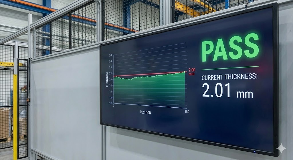
Preventive maintenance is the most effective strategy to avoid unexpected sensor failures. Establish a regular maintenance schedule. Daily, operators should perform a quick visual check and wipe down accessible sensor lenses. Weekly, inspect cable integrity and connector tightness. Monthly, conduct a more formal performance verification. For height sensors, this might involve running a test program on a flat plate and verifying the height deviation is within tolerance. Calibrate sensors according to the manufacturer's intervals using certified calibration tools. Keep a log of all maintenance activities and any minor issues observed; this history is invaluable for diagnosing recurring problems.
When repair is necessary, safety is paramount. Always lock out and tag out the machine's power before working on any component. For board-level repairs on sensor electronics, such as replacing a blown voltage regulator or damaged output transistor, ensure you have proper ESD (electrostatic discharge) protection and soldering equipment. However, many modern sensors are modular and sealed. Often, the most economical and reliable repair is a direct unit replacement. When sourcing a replacement, match the part number exactly. Pay close attention to the output type (PNP/NPN, analog, IO-Link), sensing range, voltage, and mechanical housing. After installing a new sensor, calibration and parameterization are mandatory. Input the correct parameters into the PLC or CNC, and run a series of tests to confirm proper operation before resuming production.
In conclusion, a methodical approach to laser cutting sensor maintenance—combining proactive cleaning, regular performance checks, systematic diagnosis, and safe repair practices—dramatically enhances machine reliability. Investing time in understanding these critical components pays dividends through improved uptime, consistent product quality, and reduced long-term operational costs. Training maintenance personnel on these specific procedures ensures that sensor issues are resolved swiftly and correctly, keeping your laser cutting system at peak performance.